5-14
5-3
Control sample rate and schedule
5-3-1
Control sample rate (a 07)
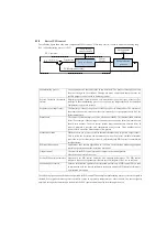
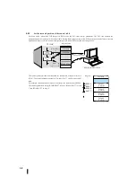
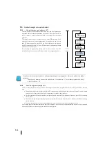
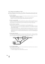
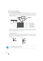
The CPU mains are in the flowchart shown on the right. The figure on the
right shows the tasks that are performed on each PLC scan when the CPU is
in RUN mode. The PID control operation is executed after the ladder
program.
The sample rate of control is simply the cycle of the PID operation. Each
operation creates a new control output value. The sample rate can be set to
the CPU in the range of 50 ms to 99.99 sec. Most controls do not require a
new PID operation for each PLC scan. PID control may perform operations
only once every 1000 scans.
By selecting the appropriate sample rate for each control, the CPU
automatically plans and executes PID operations on the appropriate scan.
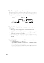
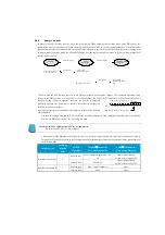
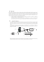
Note: Since the automatic transfer of analogue input/output is not supported, it must be written in a ladder
program.
This is done by selecting direct access with a 36 and a 37 in the ladder program and writing 1
in bit 15 of a 00.
5-3-2
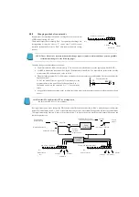
Select the optimal sample rate
There is no sample rate that fits any control. Good sample rates must be compromised to meet various guidelines at the same
time.
The required sample rate is proportional to the PV response time to the change in control output. Typically, a slow sample
rate is used for a long process, and a fast sample rate is used for a short process.
The fast sample rate provides smoother control output and accurate PV performance. However, more CPU processing
time is spent.
The slower sample rate provides rough control output and less accurate PV performance. However, the CPU processing
time is reduced.
Excessive sample rates can cause system instability, especially when set points or disturbances occur.
As a starting point, determine a sample rate that is fast enough to control to avoid control instability (which is very important).
Follow the procedure on the next page to find the first sample rate.
PLC
スキャン
入力転送
周辺装置
サービス
ラダー
プログラム
PID
ループ
演算
内部の自己診断
出力転送
PLC
Scan
Input
transmission
Peripheral
device
service
Laddar
program
PID loop
calculation
Inner
self-diagnosis
Output
transmission
Summary of Contents for Kostac SJ-Ether Series
Page 1: ...English version of the KOSTAC SJ Ether series user s manual SJ ETHER USER M...
Page 12: ......
Page 13: ...1...
Page 14: ......
Page 88: ......
Page 89: ......
Page 113: ...3 24 Note Refer to 6 3 3 Module Assembly for connections and locks between modules...
Page 153: ......
Page 156: ...flashing OFF Not sent H W RX Green flashing Receiving H W OFF Not received H W...
Page 161: ...4 8...
Page 221: ......
Page 310: ...Chapter 7 Maintenance...
Page 311: ......


