5-28
5-7-2
Remote set point (SP) position
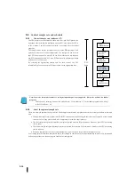
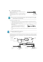
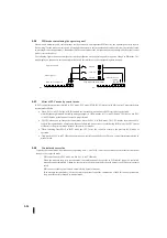
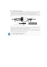
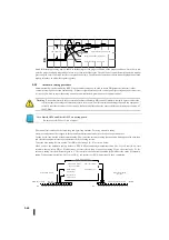
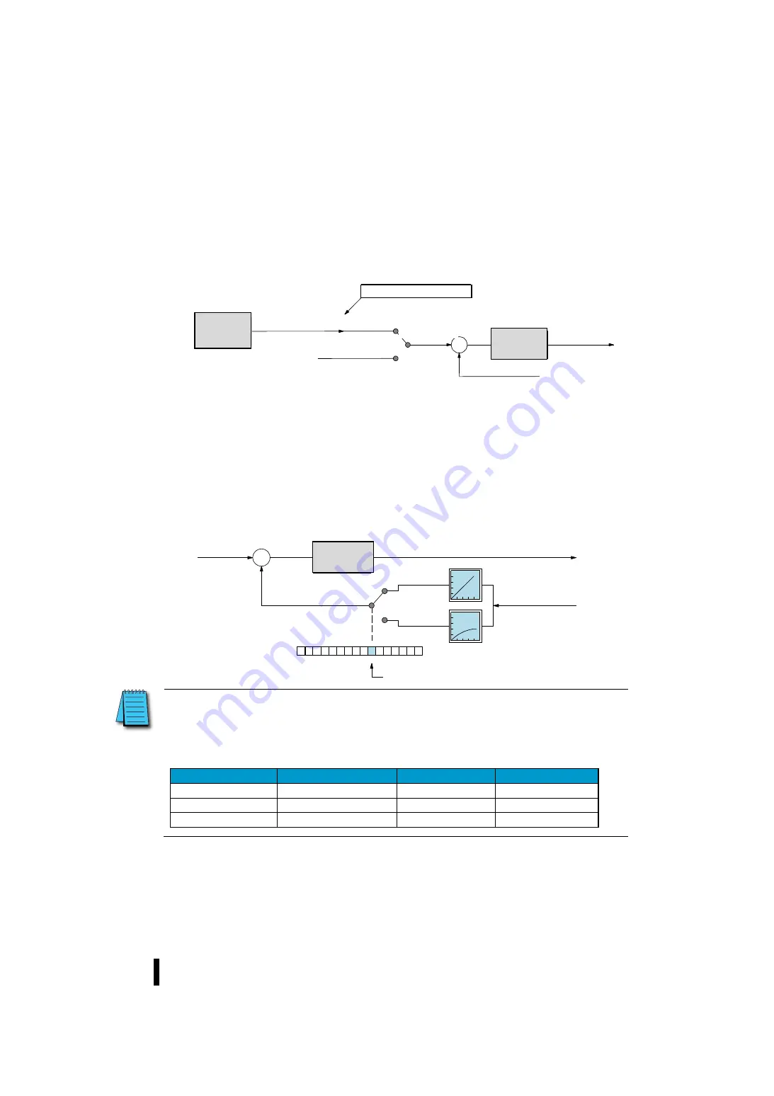
The PID control controller has the built-in ability to select two sources in the current control mode. See the illustration below.
When PID control is in automatic or manual mode, read the set point from R+02 of the table position. If you use cascade mode
for control, it must be programmed to write data to the remote SP pointer in the control parameter table.
The remote SP pointer is located at position R+32 of the control table. For cascade (create minor loops) control, you must
program the control output of the measure loop to write the address to this location. Find the starting position of the parameter
table in the measure loop and add 05 to it.
If you know the address, you can easily set it to a remote SP pointer using the PID control dialog box for KPP.
5-7-3
Configuration of process variables (PV)
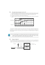
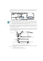
Process variable input to each control is an input value that is controlled to be equal to the set point (SP). Change to the next set
point as soon as possible. Most sensors used for process variables are primarily linear response curves. Most temperature
sensors traverse the detection range linearly. However, the square control characteristics are used for input of diverters such as
apertured diverters. Therefore, the square root extraction function is required before the signal is used in the linear control
system (such as PID).
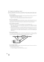
Square root extraction is effective in amplifying the flow rate. However, to do this, the cost of the sensor package is added. The
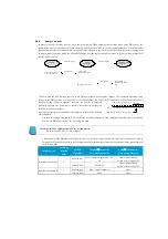
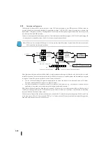
PV input for PID control can be selected from the Square Root Extraction function as shown below. Bit 6 of PID mode setting
R+00 can be used to select whether to perform normal (linear) PV or square root extraction.
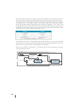
Note: When using PV square root extraction, you must adjust the SP measurement. The square root of the PV is
the PV input and PID control controls output. Split the required SP value at the square root of the
analogue value and put the result in the R+02 position, which is the SP value. This reduces the resolution
of the SP. Many flow controls do not require precision. From the data format you are using, SP uses one
of the following formulas:It is good to set the SP upper limit at the beginning of the tolerance.
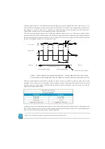
Data format
Scale of the SP
SP Scope
PV Scope
12 bits
SP=PV input/64
0 – 64
0 – 4095
15 bits
SP=PV input/181.02
0 – 181
0 – 32767
16 bits
SP=PV input/256
0 – 256
0 – 65535
+
-
R+32
XXXX
プロセス変数
ループテーブル
リモート
SP
ポインタ
別のループ
(上位ループ)
ループ演算
制御出力:
R
+
05
カスケード
セットポイント
通常の
SP
:
R
+
02
自動
/
手動
カスケードループ
(下位ループ)
ループ演算
制御出力
+
–
0
1
3
4
5
6
7
8
9
10
11
12
13
14
15
2
Bit
0
1
線形
PV/2
乗根
PV
の選択
セットポイント
プロセス変数
制御出力
線形
PV
2
乗根
PV
PID
モード
1
設定ワード:
R
+
00
ビット
ループ演算
Control
output
Set point
Process variable
Loop
calculation
Loop table
XXXX remote SP pointer
Other loop
(Upper loop)
Loop
calculation
Cascade loop
(Lower loop)
Automatic / Manual
Cascade
Normal SP
Control
output
Loop
calculation
Control
output
Process variable
Bit
PID mode 1 setting word
Linear PV
Square
root PV
Set point
Selection of linear
PV/square root PV
Summary of Contents for Kostac SJ-Ether Series
Page 1: ...English version of the KOSTAC SJ Ether series user s manual SJ ETHER USER M...
Page 12: ......
Page 13: ...1...
Page 14: ......
Page 88: ......
Page 89: ......
Page 113: ...3 24 Note Refer to 6 3 3 Module Assembly for connections and locks between modules...
Page 153: ......
Page 156: ...flashing OFF Not sent H W RX Green flashing Receiving H W OFF Not received H W...
Page 161: ...4 8...
Page 221: ......
Page 310: ...Chapter 7 Maintenance...
Page 311: ......

