5-5-5
Changing method of control mode
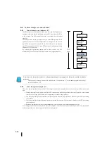
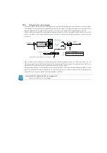
Requests that the control operation mode be changed in the first three bits
of PID control setting 1 (R+00).
These mode request bits are usually "000". To request a mode change, the
corresponding bit must be reset to "1" in one scan. The PID control
controller automatically resets to "000" after reading the mode change
request.
The mode change request method is as follows.
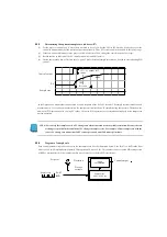
The PID monitor for KPP is the easiest way. Click on one of the radio buttons to set the appropriate bits for KPP.
Use KPP to monitor the contents of the 4-digit BCD/hexadecimal value R+00. You must add the correct mode bit to the
current value (OR) and enter a new value in R+00.
When the ladder program PLC is RUN mode, the ladder circuit can request any control mode. This is required after the
application starts.
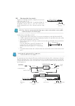
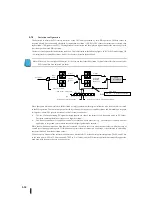
To SET the mode bit (not using the OUT command), use the
program shown to the right. When I0 changes from 0 to > 1,
the ladder circuit sets the automatic bit = 1. The controller
resets.
As a general method of operation panel, interface the ladder circuit with the operator panel to set the mode bit as shown
above.
Note: DirectSOFT4 and DirectSOFT5 are not supported.
Be sure to use KPP Ver1. 5.0.0 or higher.
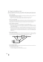
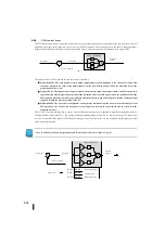
By simply requesting a mode change, the PID control controller determines whether to allow a mode change or informs the
state of the control mode. Bits 0, 1, and 2 of the alarm status word in the control table R+06 position indicate the control mode.
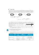
The request/monitoring function is shown in the figure below. The figure shows two possible modes-normal SP sources and
control output sources.
NOTE: These bits are not commands but mode change requests (under certain conditions, you can prohibit
certain mode changes. See the following pages).
0
1
3
4
5
6
7
8
9
10
11
12
13
14
15
2
Bit
PID
モード
1
設定ワード:
R
+
00
ビット
カスケード
自動
手動
自動モードへ
I0
SET
B2000.1
k
+
–
0
1
3
4
5
6
7
8
9
10
11
12
13
14
15
2
Bit
0
1
3
4
5
6
7
8
9
10
11
12
13
14
15
2
Bit
別のループからの
制御出力
通常の入力源
カスケード
セットポイント
自動
/
手動
偏差
ループ演算
プロセス変数
モード選択
オペレータからの入力
手動
自動
/
カスケード
制御出力
PID
モード
制御
PID
モード
1
設定ワード:
R
+
00
モード要求
カスケード
自動
手動
ループモードとアラームステータス:
R
+
06
ビット
モード監視
カスケード
自動
手動
ビット
To automatic mode
Loop
calculation
Control
output
Cascade
Set point
Process
variable
Automatic / Manual
Automatic / Cascade
Input from the operator
Manual
Manual
Automatic
Cascade
Mode selection
PID mode
control
PID mode 1 setting word
Loop mode and alarm status
Mode request
Manual
Automatic
Cascade
Manual
Automatic
Cascade
Control output
from other loop
Normal input source
PID mode 1 setting word
Deviation
Mode monitoring
Bit
Bit
Bit
Bit
Summary of Contents for Kostac SJ-Ether Series
Page 1: ...English version of the KOSTAC SJ Ether series user s manual SJ ETHER USER M...
Page 12: ......
Page 13: ...1...
Page 14: ......
Page 88: ......
Page 89: ......
Page 113: ...3 24 Note Refer to 6 3 3 Module Assembly for connections and locks between modules...
Page 153: ......
Page 156: ...flashing OFF Not sent H W RX Green flashing Receiving H W OFF Not received H W...
Page 161: ...4 8...
Page 221: ......
Page 310: ...Chapter 7 Maintenance...
Page 311: ......


