Chapter 2 Systems specification
2-32
2-5-4
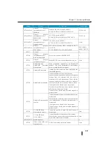
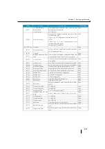
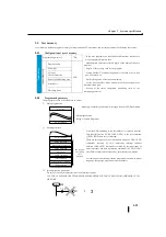
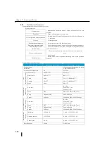
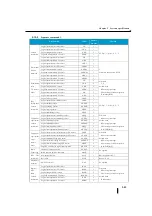
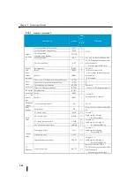
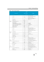
Separate description of system parameter
(1)
Program-name
This area registers the name for program identification.
(2)
Passwords
Setting the password limits the functions that can be operated. There are two types, normal and restricted.
①
Normal password
You register the password with an 8-digit number (BCD).
②
Restricted password
Use hexadecimal A as the most significant password.
③
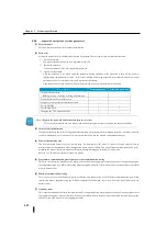
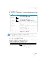
Open/Close Password
After the password is set, when either the password closing operation or the operation to turn off the power is
implemented, the password is closed . In this state, reading and writing programs are prohibited, and only monitor
operations such as I/O, internal relays, and registers are permitted.
Open the password (open operation). When the password is opened, all operations are enabled.
F e a t u r e
Normal password
Restricted password
Program edit operation
Reading, writing, rewriting, deleting, and inserting
×
×
System Parameter Setting Operation
×
×
Program, system parameter transfer operation
×
×
Forced ON/OFF
×
○
Forced Data Write
×
○
Changing the CPU operation mode
×
○
Note: • Register the password and turn off/on the power to close.
・
If you forget your password, you cannot read and write programs. Handle the password function carefully.
(3)
I/O array check instruction
Configure whether to check the I/O alignment before turning off the power when turning on the power. Normally, when the
system is determined, set "Array check" to prevent malfunction when the module configuration changes.
(4)
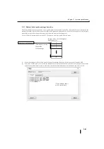
Power failure holding area
The five functional memory areas of internal relay (M), data register (R), timer (T), counter (C), and stage (S) can be
prevented from being turned on/off or disappearing due to a power failure. The power failure holding area can be set by
mounting the battery. Be sure to mount the battery when maintaining power failure for a long time.
Refer to 2-10 "Battery present/not present" for details.
(5)
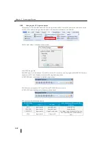
Programmer communication/general purpose serial communication setting
This area sets the station number, mode, parity, and speed of the programmer communication port and general-purpose
serial communication port. When transferring data or programs using the CCM protocol, this is set when there is a problem
with the default value.
(6)
Ethernet communication setting
This is the area to set the IP address, gateway address, and subnet mask of the Ethernet communication port. When
transferring data or programs using the Ethernet communication function, this is set when there are problems with the
default values.
(7)
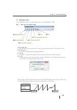
Watchdog timer
This is the setting area of the timer that monitors traffic congestion during user program execution. During program errors
or program debugging, it detects that the process has entered an infinite loop and is uncontrollable. Execute the program,
check the scan time, and set it to the appropriate value.
Summary of Contents for Kostac SJ-Ether Series
Page 1: ...English version of the KOSTAC SJ Ether series user s manual SJ ETHER USER M...
Page 12: ......
Page 13: ...1...
Page 14: ......
Page 88: ......
Page 89: ......
Page 113: ...3 24 Note Refer to 6 3 3 Module Assembly for connections and locks between modules...
Page 153: ......
Page 156: ...flashing OFF Not sent H W RX Green flashing Receiving H W OFF Not received H W...
Page 161: ...4 8...
Page 221: ......
Page 310: ...Chapter 7 Maintenance...
Page 311: ......

