5-10
PV analogue filters
Noise-containing PV signals are controlled because they make tuning difficult and the output tries to respond to the top and
trough of the PV.
The force becomes more extreme than necessary. To further stabilize PID control, you can filter the PV input. The method uses
a ladder circuit to obtain the same result.
5-10-1
Analog filter with built-in PV automatic transfer function
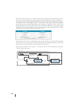
For analog input (PV value) of the PV auto-transfer function, there is a PV input filter with a selectable primary delay. This is
especially useful when you are using
auto-tuning the closed-loop method. It is recommended to use this filter when you are
using auto tuning, as shown in the figure below. You can disable the filter after automatic tuning. Alternatively, if the PV input
signal varies, you may continue to use the filter.
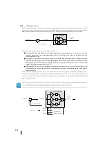
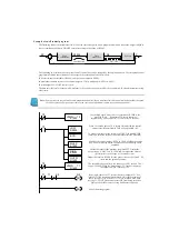
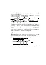
Bit 2 of PID mode setting 2 is the set bit of the PV input filter (0 = invalid, 1 = enabled) of the primary delay. The roll-off
frequency of the primary delay PV input filter is set using register R+24 in the control parameter table. The filter constant data
format is BCD, which means the decimal point 00X.X:
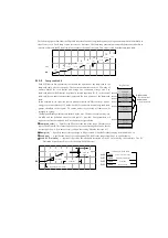
It is recommended to use KPP for automatic tuning. The time of each auto-tuning cycle depends on the amount of process. A
slowly changing PV requires a longer automatic tuning cycle time. When automatic tuning is complete, the proportional,
integral, and differential gain values automatically enter R+10, R+11, and R+12 at the control table positions, respectively. The
sample time for R+07 is also automatically updated. By measuring the PV response of the closed-loop due to the output step
change, the validity of the value generated by automatic tuning can be tested. An explanation of how to do this can be found in
the Tuning Procedure section.
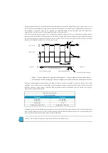
The built-in filter uses the following algorithm.
Yi=k(xi-yi-1)+yi-1
Yi: Current output of the filter
Xi:Xi:Current input to the filter
Yi-1: Output before filter
K: PV analog input filter coefficient
Note: DirectSOFT4 and DirectSOFT5 are not supported.
Be sure to use KPP Ver1. 5.0.0 or higher.
Note: Use the PV auto-transfer function.
+
–
0
1
3
4
5
6
7
8
9
10
11
12
13
14
15
2
Bit
0
1
R+24
XXXX
ループ演算
制御出力
プロセス変数
制限なしの
PV
PID
モード
2
設定:
R
+
01
PV
フィルタの
オン
/
オフ
ループテーブル
フィルタ定数
制限付きの
PV
ビット
Loop
calculation
Control
output
Process variable
Unlimited PV
Limited PV
Loop table
Filter fixed number
ON/OFF of
PV filter
PID mode 2 setting
Bit
Summary of Contents for Kostac SJ-Ether Series
Page 1: ...English version of the KOSTAC SJ Ether series user s manual SJ ETHER USER M...
Page 12: ......
Page 13: ...1...
Page 14: ......
Page 88: ......
Page 89: ......
Page 113: ...3 24 Note Refer to 6 3 3 Module Assembly for connections and locks between modules...
Page 153: ......
Page 156: ...flashing OFF Not sent H W RX Green flashing Receiving H W OFF Not received H W...
Page 161: ...4 8...
Page 221: ......
Page 310: ...Chapter 7 Maintenance...
Page 311: ......


