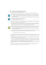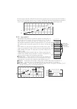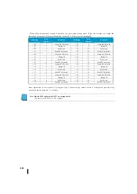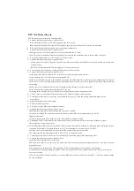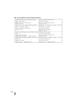
Example of on/off control program
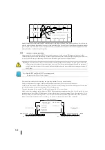
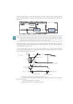
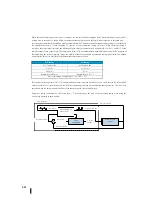
The following ladder circuit indicates ON/OFF of the control output in a time-proportional manner. It uses the output coil Q0 to
convert continuous output to ON/OFF control according to the value of R2005.
The following two timers are used to create on/off control, but can be changed by the application used. The time proportional
program must match the resolution of the output to the resolution of the T0 time axis.
The start of the control table is R2000, and the control output is R2005.
Assume that the data format of the control output is 12 bits, unsigned. (0-FFF or 0-4,095)
Set the output of ON/OFF control to Q0.
The time axis (full cycle) of the on/off waveform is 10 seconds. Count up to 1000 (10 seconds) in 0.01 second increments using
a fast timer.
Note :
Some processes are too fast for time-proportional control. If you want to select this control method, consider the speed
of the user process. For processes that are too fast to be proportional to time, use continuous control.
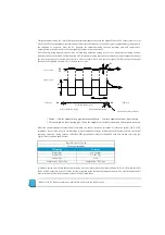
PV
+
–
R2005
SP
Q0
P
V
on/off
オン
/
オフ
連続
ループ演算
時間比例
プロセス
メインの時間軸に、高速タイマ
(0.01
秒の分解能
)
を使用。
K1000
は
10
秒のプリセット。
T0
のB接点は、タイマをオートリセットする。
T0
は
10
秒毎に1スキャン
ON
する。
10
秒経過すると、
T0
は
ON
し、ループテーブル
R+05
の
R2005
から
制御出力値(
2
進数)を読み込む。
MULS,DIVS,
及び
HTMR
命令の形式に合わせるため、アキュムレータ
の値を
BCD
形式に変換する。
1,000
を制御出力
(BCD)
に掛ける。次の
DIVS
命令に結合されるこの
ステップでは、範囲を
0-1000
に変換する。
前のステップの結果を
4095
に分割する。これは
0-4095
から
0-1000
に出力範囲の変換を行い、それは
10
秒タイマ範囲におけるタイマ時
間の数に合致する。
R1400
に結果を出力。これは
2
番目のタイマのプリセット値で、任意
の位置。
2
番目の高速タイマが
0.01
秒きざみで数えられます、その範囲は
0-1000
です。このタイマの出力、
T1
はプリセットに到達した時、出
力コイル
Q0
は
OFF
になる。
T1
のB接点を使用して、
T1
タイマ出力を逆にする。その結果、
ON/OFF
制御出力が
10
秒の周期の最初に
ON
する。
T1
が
ON
の時、
Q0
は
OFF
になる。
T1
がリセットしたスキャン、
LDNEQ
接点は
Q0
への通電を防ぎます。
Q0
はループのアクチュエータ、ヒータ等に行
きます。
メインプログラムの終了。
T0
LDW
R2005
BCD
OUTW
R1400
END
T1
OUT
Q0
MULS
K1000
T0
HTMR
R1400
T1
T0
HTMR
K1000
T0
K0
T1
DIVS
K4095
Loop
calculation
Time
proportion
Process
Continuation
ON / OFF
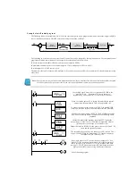
Use the high speed timer (0.01 sec resolution). K1000 is the
preset of 10 sec. B contact of T0 resets the timer
automatically. T0 becomes ON (1 scan) every 10 seconds.
When 10 seconds passes, T0 is turned ON and read the control
output value (Binary) from R2005 of Loop table R+05.
To make it suitable for the format of MULS, DIVS and HTMR
command, turns the value of the accumulator into BCD format.
Multiply the control output (BCD) by 1,000. Making the scope
be 0-1000 in this step which connects it to the following DIVS
command.
Divide the result of the previous step into 4095. It turns the
output scope ‘0-4095’ into ‘0-1000’ and it matches the value of
the timer time in the scope of 10 seconds timer.
Output the result to R1400. It is the preset value of the second
timer and the optional position.
The second high-speed timer can count every 0.01 second. The
scope is 0-1000. When the timer output ‘T1’ reaches the preset,
the output coil ‘Q0’ is turned OFF.
By using B contact of T1, reverse the timer output of T1. As a
result, ON/OFF control output is turned ON at the beginning of
the 10 seconds cycle. When T1 is ON, Q0 is turned OFF. Scan
reset by T1, LDNE Q contact prevents Q0 from being turned on.
Q0 is used for the actuator of loop and heaters and so on.
End of the main program.
Summary of Contents for Kostac SJ-Ether Series
Page 1: ...English version of the KOSTAC SJ Ether series user s manual SJ ETHER USER M...
Page 12: ......
Page 13: ...1...
Page 14: ......
Page 88: ......
Page 89: ......
Page 113: ...3 24 Note Refer to 6 3 3 Module Assembly for connections and locks between modules...
Page 153: ......
Page 156: ...flashing OFF Not sent H W RX Green flashing Receiving H W OFF Not received H W...
Page 161: ...4 8...
Page 221: ......
Page 310: ...Chapter 7 Maintenance...
Page 311: ......


