5-7
Data offset
In many batch process applications, sensors and actuators interface with SJ-Ether analog modules using 4-20 mA signals. Since the
zero point is 4 mA instead of 0 mA, this signal type has a built-in offset of 20%. However, remember that the analog module converts
the signal to data and simultaneously removes the offset. For example, the 4-20 mA signal is converted to a hexadecimal number of
0000-0FFF or a decimal number of 0-4095. In this case, the 12-bit unsigned data format is selected and the ladder program is used to
appropriately copy the data between the control table and analog modules.
PV offset - If you have a PV value that contains 20% offset, then convert the value to zero offset by subtracting the
beginning of the range by 20% and multiplying by 1.25.
Control Output - In a device with a 20% control output offset, the ladder program writes a value equal to the offset to the
bias register (R+04) before moving from manual to automatic mode. PID control sees this offset as part of the process.
5-7-1
Set point (SP) limitations
The set point of the control table position R+02 represents the target value of the process variable. After you select the data
format for these variables, you can set a limit value for the range of SP values that are used for PID control. Because many
controls rewrite set points at various times, they have two or more sources. Setting limits protects the process from bad SP
values.
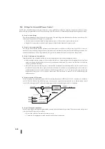
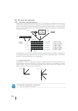
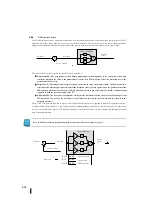
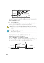
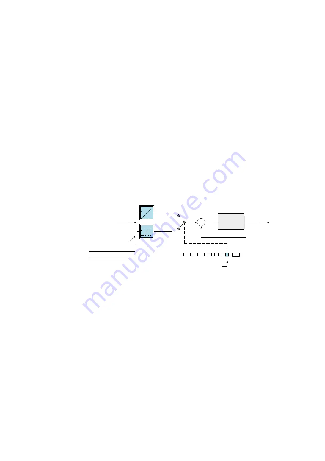
In the figure below, the marginal feature is enabled by turning on bit 3 of PID mode 2 R + 01. When enabled, R+26 and R+27 in
the control table are the lower and upper limits of the SP, respectively. PID control uses this limit internally. Any value can be
written to R+02 at any time.
PID control checks the upper and lower limits of these SPs before each calculation. This means that the limit setting can be
changed with the ladder circuit while the process is in progress, and the SP input value can be limited.
+
0
1
3
4
5
6
7
8
9
10
11
12
13
14
15
2
0
1
R+26
XXXX
R+27
XXXX
SP
制限の有効
セットポイント
制限なし
ループ演算
制御出力
制限あり
プロセス変数(
PV
)
ループテーブル
SP
上限
SP
下限
PID
モード
2
設定ワード:
R
+
01
ビット
-
Control
output
Set point
Process variable
PID mode 2 setting word
Loop
calculation
Bit
Loop table
SP limit is valid
Unlimited
Limited
SP upper limit
SP lower limit
Summary of Contents for Kostac SJ-Ether Series
Page 1: ...English version of the KOSTAC SJ Ether series user s manual SJ ETHER USER M...
Page 12: ......
Page 13: ...1...
Page 14: ......
Page 88: ......
Page 89: ......
Page 113: ...3 24 Note Refer to 6 3 3 Module Assembly for connections and locks between modules...
Page 153: ......
Page 156: ...flashing OFF Not sent H W RX Green flashing Receiving H W OFF Not received H W...
Page 161: ...4 8...
Page 221: ......
Page 310: ...Chapter 7 Maintenance...
Page 311: ......

