X20 system modules • Digital signal processing modules • X20CM1201
X20 system User's Manual 3.10
1323
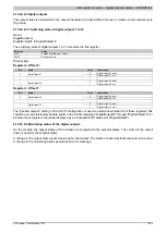
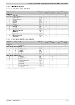
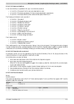
I/O states
This table shows the read display value. The parameter for the display command is 0.
Bit
Description
Value
Information
0
Input state - channel 01
0 or 1
...
...
7
Input state - channel 08
0 or 1
8 - 16
Reserved
0
17
Output state - channel 02
0 or 1
18
Reserved
0
19
Output state - channel 04
0 or 1
20
Reserved
0
21
Output state - channel 06
0 or 1
22
Reserved
0
23
Output state - channel 08
0 or 1
24 - 31
Reserved
0
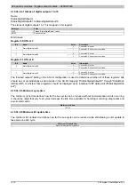
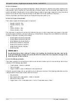
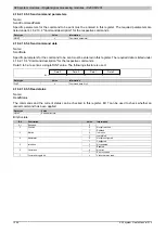
4.16.2.10.4.5 Configure counters
This command can be used to assign the hardware channels to the AB counter. With an ABR counter, the R input
can be connected to any hardware channel as the trigger signal.
Code
0x04
Parameter
See parameter structure
Data 0
See data structure
Data 1 to 3
0
Parameter structure:
Bit
Description
Value
Information
00
Pair 1 (A: channel 01, B: channel 02)
01
Pair 2 (A: channel 03, B: channel 04)
10
Pair 3 (A: channel 05, B: channel 06)
0 - 1
Counter connection pair
11
Pair 4 (A: channel 07, B: channel 08)
2 - 7
Reserved
0
Data structure:
Bit
Description
Value
Information
00
AB encoder: Up/down counter (A: timing, B: up/down signal)
01
Edge counter - channel A
10
Reserved
0 - 1
Counter mode
11
Edge counter - channel B
0
Positive
2
Counting direction
1
Negative
3 - 7
Reserved
0
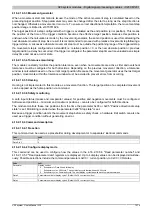
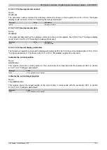
4.16.2.10.4.6 Homing
Assumes the target position of the last successful movement step as a reference position.
Code
0x05
Parameter
0
Data 0 to 3
Home position
4.16.2.10.4.7 Stops the movement.
The movement step in progress is stopped. This command always results in a movement error.
Code
0x06
Parameter
0
Data 0 to 3
0
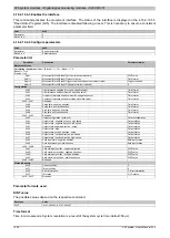
4.16.2.10.4.8 Acknowledge movement error
The movement error is is cleared. If this command is executed when the error is still present, the current position
is assumed as the target position. The basis of the relative position becomes unclear.
Code
0x07
Parameter
0
Data 0 to 3
0
Summary of Contents for X20 System
Page 2: ......

