X20 system modules • Motor controllers • X20SM1426
1990
X20 system User's Manual 3.10
Module configuration 2
Name:
StartLatch
TriggerEdgePos
TriggerEdgeNeg
StartTrigger
TriggerEdge
ClearError
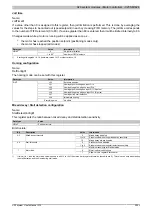
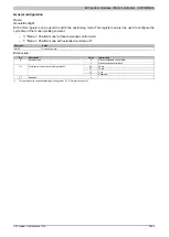
The trigger functions for the stepper motor can be configured with this register.
Data type
Value
USINT
See bit structure.
Bit structure:
Bit
Description
Value
Information
0
The latch function for stepper motor position is deactivated at
the negative edge of this bit
0
Latch function for stepper motor
Latch byte
1
The latch function for stepper motor position is deactivated at
the positive edge of this bit
00
Latch position of stepper motor, unconditional
01
Latch position of stepper motor at positive edge on input DI 3
10
Latch position of stepper motor at negative edge on input DI 3
1 - 2
Latch mode for stepper motor
TriggerEdgePos (Bit 1)
TriggerEdgeNeg (Bit 2)
11
Reserved
0
Trigger edge (input DI 4) = positive
3
TriggerEdge
1
Trigger edge (input DI 4) = negative
4
Enable trigger (when changes occur)
StartTrigger
x
0
No effect
5
ClearError
1
Error acknowledgment for the motor (for more info, see "Error
6 - 7
Reserved
-
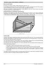
Trigger function procedure:
•
Select the desired trigger edge using bit 3
•
Enable the trigger function by changing the state of bit 4. When this bit changes, usSinceTrigger (µs counter)
is cleared.
•
When the trigger event occurs, usSinceTrigger (µs counter) is started.
•
The usSinceTrigger counter cannot overrun, i.e. it is stopped at 2
16
and retains this value until the next time
the trigger function is activated.
The trigger function can be re-activated at any time by changing the state of bit 4, regardless of whether a trigger
event has occurred or if usSinceTrigger has reached the maximum value.
Summary of Contents for X20 System
Page 2: ......


