X20 system modules • Motor controllers • X20SM1436
X20 system User's Manual 3.10
2041
Motor StepX
Name:
MotorStep0 to MotorStep3
These registers are used to specify the number and direction of steps that must be carried out by the module during
the next X2X cycle, and to select the motor current (see also "Holding current, rated current and maximum current").
Data type
Value
UINT
See bit structure.
Bit structure:
Bit
Description
Value
Information
0 - 12
Number of steps for the module to move during the next X2X
cycle
x
0
Positive
13
Direction of movement
1
Negative
00
Motor not powered
01
Holding current
10
Rated current
14 - 15
Selection of motor current
11
Maximum current
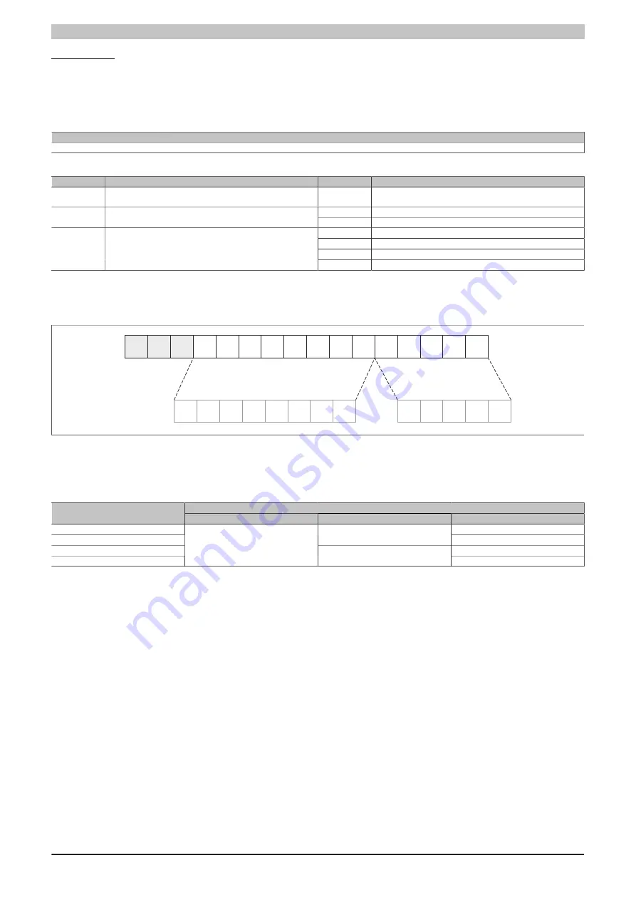
Depending on the required resolution and maximum configurable speed, "Module configuration 1" can be used to
specify which bit position is used as the 1's position for full steps (see bits 5 and 6 of Module configuration 1).
Example for 5-bit microsteps (set bits 5 and 6 of the module configuration to binary 00):
15
0
14 13 12
11 10
9
8
7
6
5
4
3
2
1
7
6
5
4
3
2
1
0
0
4
3
2
1
Full steps
Microsteps
The number of transfer values per X2X cycle is specified by bits 3 and 4 in "Module configuration 1" (see "Module
configuration 1"). If only one transfer value (bits 3 and 4 = 00) is specified, then the motor is advanced by MotorStep0
until the next X2X cycle. If 2 or 4 transfer values are specified, then the X2X cycle is divided accordingly.
Example: X2X cycle = 1 ms (1000 μs)
Number of transfer values (see Module configuration 1)
Time
1 (bits 3 - 4 = 00)
2 (bits 3 - 4 = 01)
4 (bits 3 - 4 = 10)
0 - 250 μs)
MotorStep0
250 - 500 μs)
MotorStep0
MotorStep1
500 - 750 μs)
MotorStep2
750 - 1000 μs)
MotorStep0
MotorStep1
MotorStep3
Summary of Contents for X20 System
Page 2: ......


