X20 system modules • Digital signal processing modules • X20DS1828
X20 system User's Manual 3.10
1367
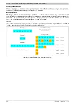
FlatStream operation
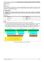
When using FlatStream, the communication direction is enormously important. For sending data to a module ("out-
put" direction), the Tx bytes are used. For receiving data from a module ("input" direction), the Rx bytes are used.
The "OutputSequence" and "InputSequence" registers are used to control and ensure that communication is taking
place properly, i.e. the transmitter issues the directive that the data should be accepted and the receiver acknowl-
edges that a sequence has been transmitted successfully.
Transporting the payload data and the control bytes
Name:
TxByte1 to TxByteN
RxByte1 to RxByteN
(The value the number N is different depending on the bus controller model used.)
The Tx and Rx bytes are cyclic registers used to transport the payload data and the necessary control bytes. The
number of active Tx and Rx bytes is taken from the configuration of the "OutputMTU" and "InputMTU" registers,
respectively.
In the user program, only the Tx and Rx bytes from the CPU can be used. The corresponding counterparts are
located in the module and are not accessible to the user. For this reason, names were chosen from the CPU point
of view.
•
"T" - "Transmit" → CPU
transmits
data to the module.
•
"R" - "Receive" → CPU
receives
data from the module.
Data type
Value
USINT
0 to 65535
Control bytes
In addition to the payload data, the Tx and Rx bytes also transmit the necessary control bytes. These control bytes
contain additional information about the data stream so that the receiver can reconstruct the original message from
the transmitted segments.
Bit structure of a control byte
Bit
Name
Value
Information
0 - 5
SegmentLength
0 - 63
Size of the subsequent segment in bytes (default: Max. MTU size - 1)
0
Next control byte at the beginning of the next MTU
6
nextCBPos
1
Next control byte directly after the end of the current segment
0
Message continues after the subsequent segment
7
MessageEndBit
1
Message ended by the subsequent segment
SegmentLength
The segment length lets the receiver know the length of the coming segment. If the configured segment length
is insufficient for a message, then the information must be distributed over several segments. In these cases, the
actual end of the message is detected using bit 7 of the control byte.
Information:
The control byte is not included in the calculation to determine the segment length. The segment length
is only derived from the bytes of payload data.
nextCBPos
This bit indicates the position where the next control byte is to be expected. This information is especially important
when using the "MultiSegmentMTU" option.
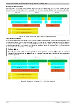
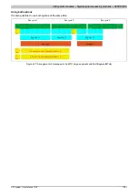
When using FlatStream communication with multi-segment MTUs, the next control byte is no longer expected in
the first Rx byte of the subsequent MTU, but directly after the current segment.
Summary of Contents for X20 System
Page 2: ......


