X20 system modules • Analog input modules • X20AI1744, X20AI1744-3
136
X20 system User's Manual 3.10
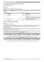
4.3.2.11 Register description
4.3.2.11.1 Function model 0 - Standard
Read
Write
Register
Name
Data type
Cyclic
Acyclic
Cyclic
Acyclic
2
USINT
●
4
DINT
●
16
USINT
●
18
UINT
●
32
USINT
●
1)
X20AI744
: from firmware version 8 / upgrade 1.3.0.0;
X20AI744-3
: from firmware version 8 / upgrade 1.2.0.0
4.3.2.11.2 Function model 1 - Multiple sampling
In this function model, the AD converter is operated in synchronization with X2X Link using a fixed ADC cycle time
(configurable as 50 or 100 µs).
The module returns between 3 and 10 measured values per X2X cycle depending on the configuration. With an
X2X cycle time of 400 µs and ADC cycle time of 50 µs, exactly 8 measurements are performed and the module
can return 8 values (strain gauge value 01 to strain gauge value 08).
If a longer cycle time is used, the values returned correspond to the last measurements. If using an X2X cycle time
that is not a whole number multiple of the ADC cycle time, then the conversion cannot be synchronized with X2X
Link. In this case, the module outputs the invalid value 0x8000.
Example 1
With an X2X cycle time of 800 µs, 16 measurements are performed per X2X cycle. The first 6 measured values
are discarded; the last 10 measured values are provided by the module.
With a shorter X2X cycle time, the number of measured values should not exceed the number of measurements
that can actually be made. All other measured values are invalid (0x8000). To minimize the load on X2X Link, it is
possible to disable unneeded registers (see "Number of measurement values").
Example 2
If using an X2X cycle time of 300 μs, it is possible to perform 6 measurements per X2X cycle if the ADC cycle
time equals 50 µs. For this reason, only the first 6 registers are valid. The registers for the 7th through 10th mea-
sured value (AnalogInput07 to AnalogInput08) should be disabled by setting "Number of measured values" to "6
measured values" in the I/O configuration.
Read
Write
Register
Name
Data type
Cyclic
Acyclic
Cyclic
Acyclic
2
USINT
●
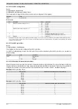
1534 + N * 4 AnalogInput0N (N = 1 to 10)
INT
●
1600
ConfigGain01_MultiSample (X20AI1744-3)
USINT
●
1603
USINT
●
4.3.2.11.3 Function model 254 - Bus Controller
In the bus controller function model, the module behaves as it does in the standard function model, with the ex-
ception that it is not synchronized to the X2X Link even if Synchronous mode is activated in the ADC configuration
register. Instead, the module behaves as if the set ADC cycle time is not a factor or multiple of the X2X cycle time
and attempts to maintain the set ADC cycle time as precisely as possible.
Read
Write
Register
Name
Data type
Cyclic
Acyclic
Cyclic
Acyclic
2
USINT
●
4
DINT
●
16
USINT
●
18
UINT
●
32
USINT
●
1)
X20AI744
: from firmware version 8 / upgrade 1.3.0.0;
X20AI744-3
: from firmware version 8 / upgrade 1.2.0.0
Summary of Contents for X20 System
Page 2: ......


