X20 system modules • Analog input modules • X20AP31x1
330
X20 system User's Manual 3.10
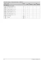
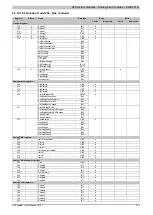
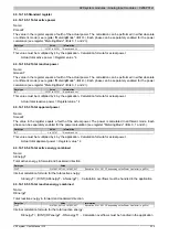
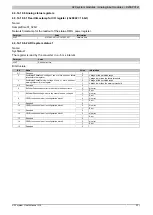
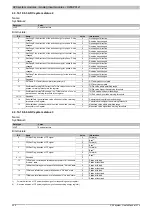
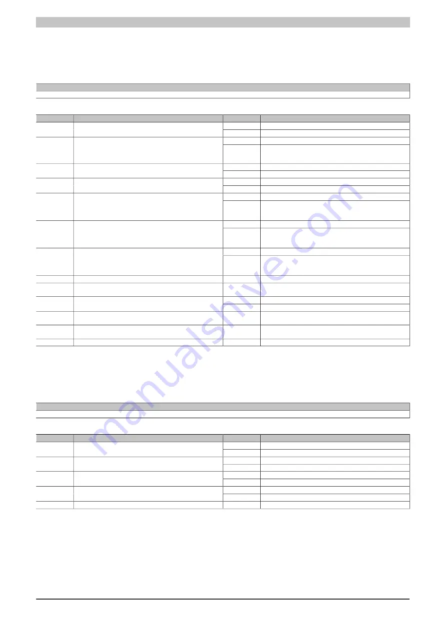
4.3.14.10.5.6 Status signals and responses
Name:
StatusInput
The signals are recorded in 200 µs intervals.
Data type
Value
UINT
See bit structure
Bit structure:
Bit
Name
Value
Information
0
Not yet calculated
0
CF1 energy pulse 1, total active energy
1
Calculated
0
Not yet calculated
1
CF2 energy pulse 2, total apparent energy, configurable
Standard:
Arithmetic sum of apparent energy, can be reconfigured via reg-
ister <MeteringMode>
1
Calculated
0
Not yet calculated
2
CF3 energy pulse 3, total active energy, fundamental wave
1
Calculated
0
Not yet calculated
3
CF4 energy pulse 4, total active energy, harmonics
1
Calculated
0
Zero cross-over not detected
4
ZX1 zero cross signal – Phase A
1
Standard:
Pulse at positive edge of the zero cross signal of the voltage
input, can be reconfigured via register "ZXConfig"
0
Zero cross-over not detected
5
ZX2 zero cross signal – Phase B
1
Standard:
Pulse at positive edge of the zero cross signal of the voltage
input, can be reconfigured via register "ZXConfig"
0
Zero cross-over not detected
6
ZX3 zero cross signal – Phase C
1
Standard:
Pulse at positive edge of the zero cross signal of the voltage
input, can be reconfigured via register "ZXConfig"
7
Reserved
0
8
DFT response sent
x
If the state in the register "ControlOutput" corresponds with the
response, then the action is complete
0
No update
9
Energy value update response sent
1
Update complete
10
Energy value response deleted
x
If the state in the register "ControlOutput" corresponds with the
response, then the action is complete
11
Energy value response set
x
If the state in the register "ControlOutput" corresponds with the
response, then the action is complete
12 - 15
Reserved
0
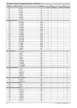
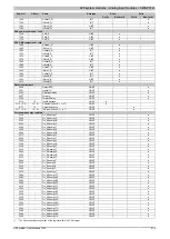
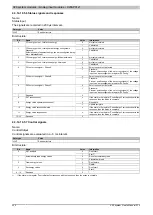
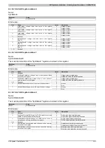
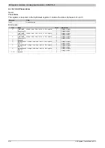
4.3.14.10.5.7 Control signals
Name:
ControlOutput
Control signals are evaluated in a ~5 ms interval.
Data type
Value
UINT
See bit structure
Bit structure:
Bit
Name
Value
Information
0
Don't start
0
DFT analysis
1
Start
1)
0
Do not automatically read
1
Automatically read energy values
1
Automatically read
0
Don't delete
2
Clear energy values
1
Delete
1)
0
Don't start
3
Set energy values
1
Start
1)
4 - 15
Reserved
0
1)
If the state in the register "ControlOutput" corresponds with the response, then the action is complete.
Summary of Contents for X20 System
Page 2: ......

