X20 system modules • Counter modules • X20DC2396
840
X20 system User's Manual 3.10
4.11.15.8.4 ABR encoder - Configuration registers
4.11.15.8.4.1 Counter state of the encoders
Name:
Encoder01 to Encoder02
The encoder values are displayed in this register.
Data type
Value
INT
-32,768 to 32,767
DINT
1)
-2,147,483,648 to 2,147,483,647
1)
Only in function model 1
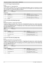
4.11.15.8.4.2 Input state of digital inputs 1 to 2
Name:
DigitalInput01 to DigitalInput02.
This register displays the input status of the encoders and the digital inputs.
Data type
Value
USINT
See bit structure.
Bit structure:
Bit
Name
Value
Information
0
0 or 1
Input state - Signal A
1
0 or 1
Input state - Signal B
2
Encoder 1
0 or 1
Input state of reference pulse
3
DigitalInput01
0 or 1
Input state - Digital input 1
4
0 or 1
Input state - Signal A
5
0 or 1
Input state - Signal B
6
Encoder 2
0 or 1
Input state of reference pulse
7
DigitalInput02
0 or 1
Input state - Digital input 2
4.11.15.8.4.3 Reading the referencing mode
Name:
ReferenceModeEncoder01 to ReferenceModeEncoder02
This register determines the referencing mode.
Data type
Value
USINT
See bit structure.
Bit structure:
Bit
Name
Value
Information
00
Referencing OFF
01
Single shot referencing
0 - 1
11
Continuous referencing
2 - 5
0
Bits permanently set = 0
00
Referencing OFF
6 - 7
11
Bits permanently set = 1
This results in the following values:
Binary
Hex
Function
00000000
0x00
Referencing OFF
11000001
0xC1
Single shot referencing
For a new start after the completed homing procedure:
•
Write value 0x00
•
Wait until bit 0 to bit 3 of the StatusInput01 register takes on the value 0. Counter
bits 4 to 7 are not erased
•
Switch homing procedure on again
11000011
0xC3
Continuous referencing
Referencing occurs at every reference pulse.
Summary of Contents for X20 System
Page 2: ......


