X20 system modules • Other functions • X20CM8281
X20 system User's Manual 3.10
2219
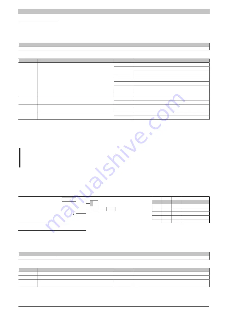
Counter configuration
Name:
ConfigOutput02
This register can be used to configure and reset the individual counters.
Data type
Value
USINT
See bit structure.
Bit structure:
Bit
Name
Value
Information
0
48 MHz
1
3 MHz
2
187.5 kHz
3
24 MHz
4
12 MHz
5
6 MHz
6
1.5 MHz
7
750 kHz
0 - 3
Counter02 (counter frequency, only with gate measurement)
8
375 kHz
0
No influence on the counter
4
ResetCounter01
1
Clear counter (at positive edge)
0
No influence on the counter
5
ResetCounter02
1
Clear counter (at positive edge)
0
Event counter measurement
6 - 7
Counter02 (operating mode)
1
Gate measurement
This register also includes configuration data in addition to the cyclic data. If the register is used cyclically and in
the init script, then the preset configuration only remains available when operated directly on the CPU. On the bus
controller, the configuration is always overwritten with 0.
However, starting with upgrade version 1.0.2.1, the cyclic bit can be hidden in order to prevent the configuration
from being overwritten.
Information:
If the counter should be cleared, this must be done using a non-cyclic write command. When doing
so, the configuration bit must be transferred together with the reset counter bit!
4.26.3.10.3.4 Positive edge input latch
Using this function, the positive edges of the input signal can be latched with a resolution of 200 µs. With the
"Acknowledge - input latch" function, the input latch is either reset or prevented from latching.
It works in the same way as a dominant reset RS flip-flop.
R
S
Q
Status
0
0
x
Do not change
0
1
1
Set
1
0
0
Reset
1
1
0
Reset
R
S
Q
Reset x
Input x
Latch x
Pos. edge
Input state of digital latch inputs 1 - 4
Name:
DigitalInputLatch01 to DigitalInputLatch04
This register is used to indicate input state of digital inputs 1 to 4 after expiration of the input filter time.
Data type
Value
USINT
See bit structure.
Bit structure:
Bit
Name
Value
Information
0
DigitalInputLatch01
0 or 1
Input state of digital input 1 after expiration of the delay time
...
...
3
DigitalInputLatch04
0 or 1
Input state of digital input 4 after expiration of the delay time
4 - 7
Reserved
-
Summary of Contents for X20 System
Page 2: ......

