X20 system modules • Analog output modules • X20AO4632-1
496
X20 system User's Manual 3.10
4.4.9.9.5 Analog output - Communication
In standard mode, the module's outputs are enabled. Based on the configuration and AnalogOutput value, they
output the corresponding current or voltage.
If the application requires time-based monitoring of the outputs, then a validation timer can be assigned to each
channel. The validation timer register assigns a validity duration to the current output value. When validation is
enabled, the module compares the validation time with the Nettime of the X2X Link. If the transferred validity
duration is exceeded, the module disables the channel and resets the output. The "safety shutdown" state will not
be reset until a new and valid validation time has been transferred. If enabled, the module reports which state it
is currently in via the channel's error status bit.
If the value of the validation timer is incremented in each task cycle, the valid validation time will be calculated
as follows:
Nettime of the X2X Link master (which the module is connected to)
+
Timespan for transferring data from the X2X Link master to the CPU (higher-level system)
+
Cycle time of task class (including tolerance)
+
Timespan for transferring the data from the CPU to the module
+
Timespan allowed by the application (e.g. for tolerating failure of an X2X Link cycle)
=
Valid validation time
The AnalogOutputEnableByte is enabled during time-based monitoring. If the timer expires prematurely, the corre-
sponding bit in the AnalogOutputOkayByte is reset and the output drops out. This provides an easy way to achieve
a defined state.
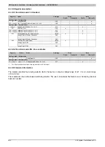
4.4.9.9.5.1 Output values of the analog outputs
Name:
AnalogOutput01 to AnalogOutput04
These registers provide the standardized output values. Once a permitted value is received, the module outputs
the respective current or voltage.
Information:
The value "0" disables the channel status LED.
Data type
Value
-32767 to 32767
Voltage; Bus controller default setting: 0
INT
0 to 32767
Current
4.4.9.9.5.2 SDC counter register
Name:
SDCLifeCount
The 8-bit counter register is needed for the SDC software package. It is incremented with the system clock to allow
the SDC to check the validity of the data frame.
Data type
Value
SINT
-128 to 127
4.4.9.9.5.3 Transfer of the timestamp
Name:
ValidationTimer01 to ValidationTimer04
When an output is being monitored, these registers must provide the timestamp which, when reached, will cause
the output to shut down automatically. The values must be provided as signed 2-byte or 4-byte values.
Data type
Values [µs]
INT
-32768 to 32767
Nettime timestamp of the current output value
DINT
-2,147,483,648
to 2,147,483,647
Nettime timestamp of the current output value
Summary of Contents for X20 System
Page 2: ......

