X20 system modules • Counter modules • X20DC2190
X20 system User's Manual 3.10
789
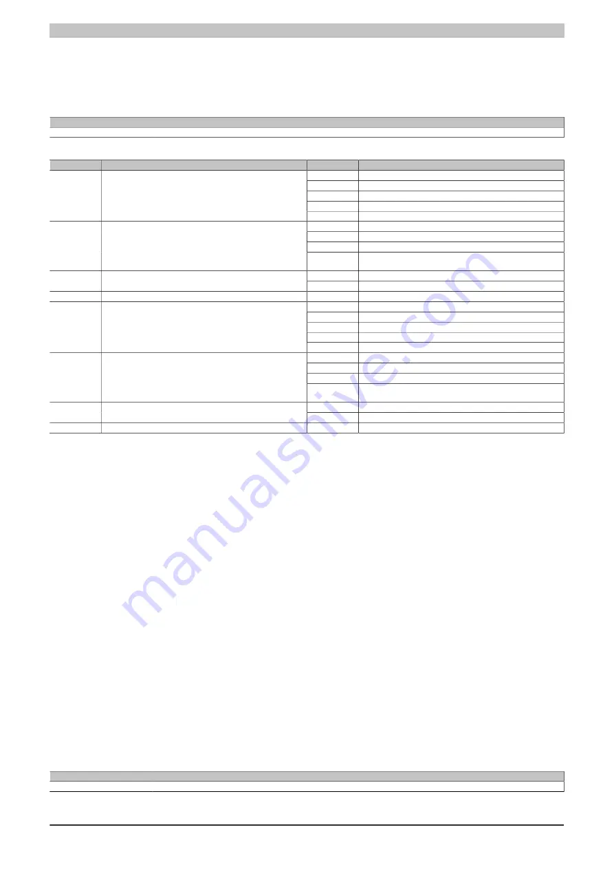
4.11.13.7.11 Channel configuration
Name:
ConfigOutput02
This register can be used to configure the individual channels.
Data type
Value
USINT
See bit structure.
Bit structure:
Bit
Description
Value
Information
000
User parameter
001
DPI/IP (Balluf)
010
EP Start/Stop (MTS)
011
Reserved
0 - 2
Transducer Rod 1
1xx
Reserved
00
Start/Stop Signal: Rising edge - rising edge
01
Start/Stop Signal: Falling edge - falling edge
10
Start/Stop Signal: Rising edge - falling edge (gate time)
3 - 4
Rod 1: Start/Stop IF type
11
Only Stop Signal: Start when signal is triggered (initialization
pulses)
0
3 x USW runtime for rod (default)
5
Rod 1: Recovery time factor, minimum time between two mea-
surements
1
2 x USW runtime for rod
6 - 7
Reserved
000
User parameter
001
DPI/IP (Balluf)
010
EP Start/Stop (MTS)
011
Reserved
8 - 10
Transducer Rod 2
1xx
Reserved
00
Start/Stop Signal: Rising edge - rising edge
01
Start/Stop Signal: Falling edge - falling edge
10
Start/Stop Signal: Rising edge - falling edge (gate time)
11 - 12
Rod 2: Start/Stop IF type
11
Only Stop Signal: Start when signal is triggered (initialization
pulses)
0
3 x USW runtime for rod (default)
13
Rod 2: Recovery time factor, minimum time between two mea-
surements
1
2 x USW runtime for rod
14 - 15
Reserved
Comment concerning bits 5 + 13
USW transducer rods require a certain recovery time between two measurements to allow the ultrasonic wave to
fade. Otherwise there is a risk of interfering with the next measurement (especially when the rod has more than
1 magnet).
Depending on the setting, the module waits at least 2 or 3 times the runtime of the ultrasonic wave for the measure-
ment rod (default = 3x). In the standard function module, the next measurement is then triggered synchronously
with the next X2XLink cycle.
The runtime measurement is based on the settings for the rod length (plus a safety margin of 100mm) and the
ultrasonic speed:
•
USW runtime = (rod 100mm) / ultrasonic speed.
For their rods, BALLUFF recommends a recovery time equal to 3 times the maximum runtime of the ultrasonic
wave for the measurement rod. This is the default setting for the module.
The setting can be switched to 2 times the runtime if the measurement rate is otherwise too slow. This may only
be done after consulting the manufacturer of the transducer rods!
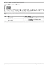
4.11.13.7.12 Rod length 1 and 2
Name:
ConfigOutput03 to ConfigOutput04
These registers are used to configure the length of the respective rod.
•
Rod length 1: ConfigOutput03
•
Rod length 2: ConfigOutput04
Data type
Value
UDINT
0 to 4,294,967,296: Resolution 1 mm
Summary of Contents for X20 System
Page 2: ......


