A.7
Power management signals
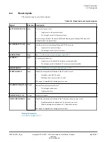
The processor has retention and non-retention signals for power management.
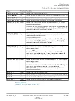
Table A-8 Non-Retention power management signals
Signal
Direction Description
CLREXMONREQ
Input
Clearing of the external global exclusive monitor request. When this signal is asserted, it
acts as a WFE wake-up event to all the cores in the processor device.
CLREXMONACK
Output
Clearing of the external global exclusive monitor acknowledge.
EVENTI
Input
Event input for processor wake-up from WFE state.
EVENTO
Output
Event output. Active when a
SEV
instruction is executed.
STANDBYWFI[CN:0]
Output
Indicates whether a core is in WFI low-power state:
0
Core not in WFI low-power state.
1
Core in WFI low-power state. This is the reset condition.
STANDBYWFE[CN:0]
Output
Indicates whether a core is in WFE low-power state:
0
Core not in WFE low-power state.
1
Core in WFE low-power state.
STANDBYWFIL2
Output
Indicates whether the L2 memory system is in WFI low-power state. This signal is active
when the following conditions are met:
•
All cores are in WFI low-power state, held in reset, or
nL2RESET
is asserted LOW.
•
In an ACE configuration,
ACINACTM
is asserted HIGH.
•
In a CHI configuration,
SINACT
is asserted HIGH.
•
If ACP has been configured,
AINACTS
is asserted HIGH.
•
L2 memory system is idle.
L2FLUSHREQ
Input
L2 hardware flush request.
L2FLUSHDONE
Output
L2 hardware flush complete.
SMPEN[CN:0]
Output
Indicates whether a core is taking part in coherency.
DBGNOPWRDWN[CN:0]
Output
Request not to power down the core:
0
Do not request that the core stays powered-up.
1
Request that the core stays powered-up.
DBGPWRUPREQ[CN:0]
Output
Core power-up request:
0
Do not request that the core is powered up.
1
Request that the core is powered up.
DBGPWRDUP[CN:0]
Input
Core powered up
0
Core is powered down.
1
Core is powered up.
A Signal Descriptions
A.7 Power management signals
100236_0100_00_en
Copyright © 2015–2017, 2019 Arm Limited or its affiliates. All rights
reserved.
Appx-A-856
Non-Confidential
Summary of Contents for Cortex-A35
Page 4: ......
Page 18: ......
Page 26: ......
Page 27: ...Part A Functional Description ...
Page 28: ......
Page 145: ...Part B Register Descriptions ...
Page 146: ......
Page 573: ...Part C Debug ...
Page 574: ......
Page 845: ...Part D Appendices ...
Page 846: ......

