ISD94100 Series Technical Reference Manual
Sep 9, 2019
Page
272
of 928
Rev1.09
IS
D
9
410
0
S
ER
IE
S
T
E
C
HN
ICA
L
RE
F
E
RE
NCE
M
AN
U
AL
6.6.5.6
PDMA Controller Transfer Bandwidth
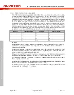
The PDMA fits into the memory system of the ISD94100 as a master on the AHB bus. Only a finite
number of PDMA transactions can occur on the AHB per second, hence there is a maximum
bandwidth possible for PDMA transfers. The PDMA controller takes multiple clock cycles to handle
requests to/from peripherals or SRAM. The PDMA controller uses round-robin priority scheme to
handle each channel. Each PDMA channel transfer (a data transaction of width byte/half-word/word
based on PDMA setting) between the peripheral’s FIFO and system SRAM takes 9 AHB clock
cycles plus 5 APB clock cycles. And the AHB clock cycles for memory-to-memory burst transfers
are listed in the table below. The user must consider the worst case time to complete outstanding
PDMA requests of all high priority channels in assessing whether there is sufficient PDMA
bandwidth for the application. If memory bandwidth utilization is too high then FIFO overflow on
peripherals can occur when PDMA request cannot be serviced in a timely manner.
Burst Size
AHB Clock Cycles
Burst Size
AHB Clock Cycles
1
14
16
74
2
18
32
144
4
26
64
284
8
42
128
564
Example:
If the frequency of HCLK is 49.152 MHz, the frequency of PCLK0 and PCLK1 is 24.576 MHz, for
each memory-to-peripheral (M2P) and peripheral-to-memory (P2M) transfer takes 19 AHB (9 + 5 *
(F
AHB
/F
APB
)) clock cycles.
Suppose I2S interface is used with a sampling rate of 48 kHz, data width of 32 bits and stereo
transmission, PDMA controller needs 48000 * 2(stereo) * 2(RX/TX) * 19 = 3,648,000 AHB clock
cycles per second to handle the data transfer rate.
If there is also a 2560000 word, 128 burst size, memory-to-memory (M2M) transfer per second
scheduled. Then this takes 2560000/128 * 564 = 11,280,000 AHB clock cycles per second.
The remaining 34,224,000 (49,152,000 – 11,280,000 – 3,648,000) AHB clock cycles can be used
for other peripheral data transfer.
Supposed that 2 channels of SPI are enabled with PDMA transfer, the maximum frequency for each
SPI bus clock should be less than 14 MHz. The calculation being:
34,224,000 (available cycles/sec) / 4(PDMA channels for SPI TX and RX) / 19 (P2M or M2P AHB
clock cycles) * 32 (FIFO width) = 14.41 MHz.

