ISD94100 Series Technical Reference Manual
Sep 9, 2019
Page
598
of 928
Rev1.09
IS
D
9
410
0
S
ER
IE
S
T
E
C
HN
ICA
L
RE
F
E
RE
NCE
M
AN
U
AL
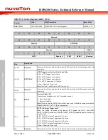
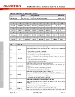
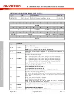
UART Modem Status Register (UART_MODEMSTS)
Register
Offset
R/W Description
Reset Value
UART_MODEMSTS
U0x14
R/W UART Modem Status Register
0x0000_0110
31
30
29
28
27
26
25
24
Reserved
23
22
21
20
19
18
17
16
Reserved
15
14
13
12
11
10
9
8
Reserved
CTSACTLV
7
6
5
4
3
2
1
0
Reserved
CTSSTS
Reserved
CTSDETF
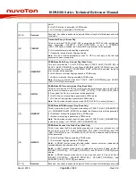
Bits
Description
[31:9]
Reserved
Reserved. Any values read should be ignored. When writing to this field always write with
reset value.
[8]
CTSACTLV
nCTS Pin Active Level
This bit defines the active level state of nCTS pin input.
0 = nCTS pin input is high level active.
1 = nCTS pin input is low level active. (Default)
Note:
Before setting this bit, TXRXDIS (UART_FUNCSEL[3]) should be set then waited for
TXRXACT (UART_FIFOSTS[31]) is cleared. When the configuration is done, cleared
TXRXDIS (UART_FUNCSEL[3]) to activate UART controller.
[7:5]
Reserved
Reserved. Any values read should be ignored. When writing to this field always write with
reset value.
[4]
CTSSTS
nCTS Pin Status (Read Only)
This bit mirror from nCTS pin input of voltage logic status.
0 = nCTS pin input is low level voltage logic state.
1 = nCTS pin input is high level voltage logic state.
Note:
This bit echoes when UART controller peripheral clock is enabled, and nCTS multi-
function port is selected.
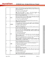
[3:1]
Reserved
Reserved. Any values read should be ignored. When writing to this field always write with
reset value.
[0]
CTSDETF
Detect nCTS State Change Flag
This bit is set whenever nCTS input has change state, and it will generate Modem interrupt
to CPU when MODEMIEN (UART_INTEN [3]) is set to 1.
0 = nCTS input has not change state.
1 = nCTS input has change state.
Note:
This bit can be cleared by writing “1” to it.


