ISD94100 Series Technical Reference Manual
Sep 9, 2019
Page
815
of 928
Rev1.09
IS
D
9
410
0
S
ER
IE
S
T
E
C
HN
ICA
L
RE
F
E
RE
NCE
M
AN
U
AL
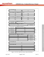
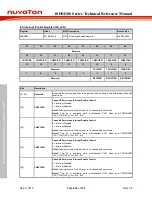
6.17.7 Register Description
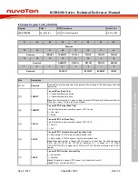
I2S Control Register 0 (I2S_CTL0)
Register
Offset
R/W Description
Reset Value
I2S_CTL0
0x00
R/W I
2
S Control Register 0
0x0000_0000
31
30
29
28
27
26
25
24
TDMCHNUM
CHWIDTH
PCMSYNC
FORMAT
23
22
21
20
19
18
17
16
RXLCH
Reserved
RXPDMAEN
TXPDMAEN
RXFBCLR
TXFBCLR
FLZCDEN
FRZCDEN
15
14
13
12
11
10
9
8
MCLKEN
Reserved
SLAVE
7
6
5
4
3
2
1
0
ORDER
MONO
DATWIDTH
MUTE
RXEN
TXEN
I2SEN
Bits
Description
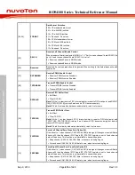
[31:30]
TDMCHNUM
TDM Channel Number
This bit fields are used to define the TDM channel number in one audio frame while PCM
mode (FORMAT[2] = 1).
00 = 2 channels in audio frame.
01 = 4 channels in audio frame.
10 = 6 channels in audio frame.
11 = 8 channels in audio frame.
[29:28]
CHWIDTH
Channel Width
This bit fields are used to define the length of audio channel. If CHWIDTH < DATWIDTH,
the hardware will set the real channel length as the bit-width of audio data which is defined
by DATWIDTH.
00 = The bit-width of each audio channel is 8-bit.
01 = The bit-width of each audio channel is 16-bit.
10 = The bit-width of each audio channel is 24-bit.
11 = The bit-width of each audio channel is 32-bit.
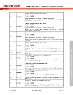
[27]
PCMSYNC
PCM Synchronization Pulse Length Selection
This bit field is used to select the high pulse length of frame synchronization signal in PCM
protocol
0 = One BCLK period.
1 = One channel period.
Note:
This bit is only available in master mode

