ISD94100 Series Technical Reference Manual
Sep 9, 2019
Page
595
of 928
Rev1.09
IS
D
9
410
0
S
ER
IE
S
T
E
C
HN
ICA
L
RE
F
E
RE
NCE
M
AN
U
AL
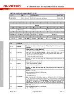
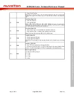
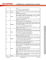
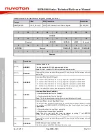
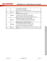
1 = Break Control Enabled.
Note:
When this bit is set to logic 1, the transmitted serial data output (TX) is forced to the
Spacing State (logic 0). This bit acts only on TX line and has no effect on the transmitter
logic.
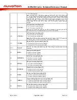
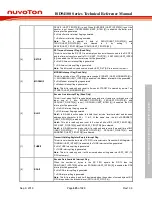
[5]
SPE
Stick Parity Enable Bit
0 = Stick parity Disabled.
1 = Stick parity Enabled.
Note:
If PBE (UART_LINE[3]) and EPE (UART_LINE[4]) are logic 1, the parity bit is
transmitted and checked as logic 0. If PBE (UART_LINE[3]) is 1 and EPE (UART_LINE[4])
is 0 then the parity bit is transmitted and checked as 1.
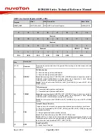
[4]
EPE
Even Parity Enable Bit
0 = Odd number of logic 1’s is transmitted and checked in each word.
1 = Even number of logic 1’s is transmitted and checked in each word.
Note:
This bit has effect only when PBE (UART_LINE[3]) is set.
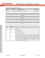
[3]
PBE
Parity Bit Enable Bit
0 = Parity bit generated Disabled.
1 = Parity bit generated Enabled.
Note:
Parity bit is generated on each outgoing character and is checked on each incoming
data.
[2]
NSB
Number of “STOP Bit”
0 = One “STOP bit” is generated in the transmitted data.
1 = When select 5-bit word length, 1.5 “STOP bit” is generated in the transmitted data. When
select 6-, 7- and 8-bit word length, 2 “STOP bit” is generated in the transmitted data.
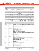
[1:0]
WLS
Word Length Selection
This field sets UART word length.
00 = 5 bits.
01 = 6 bits.
10 = 7 bits.
11 = 8 bits.

