ISD94100 Series Technical Reference Manual
Sep 9, 2019
Page
488
of 928
Rev1.09
IS
D
9
410
0
S
ER
IE
S
T
E
C
HN
ICA
L
RE
F
E
RE
NCE
M
AN
U
AL
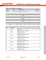
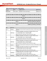
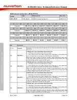
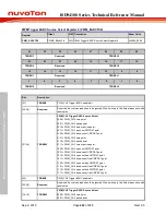
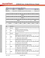
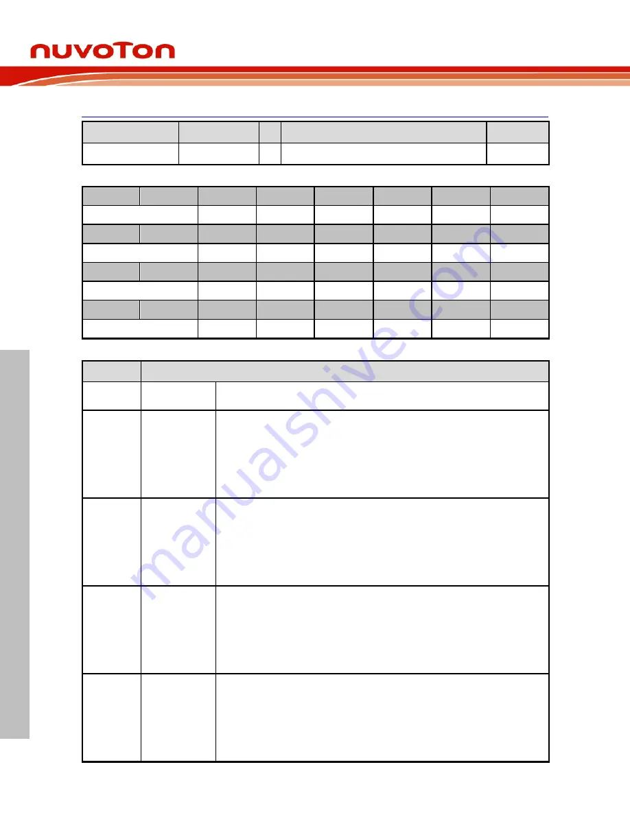
PWM Interrupt Flag Register 1 (PWM_INTSTS1)
Register
Offset
R/W Description
Reset Value
PWM_INTSTS1
0xEC
R/W PWM Interrupt Flag Register 1
0x0000_0000
31
30
29
28
27
26
25
24
Reserved
BRKLSTS5
BRKLSTS4
BRKLSTS3
BRKLSTS2
BRKLSTS1
BRKLSTS0
23
22
21
20
19
18
17
16
Reserved
BRKESTS5
BRKESTS4
BRKESTS3
BRKESTS2
BRKESTS1
BRKESTS0
15
14
13
12
11
10
9
8
Reserved
BRKLIF5
BRKLIF4
BRKLIF3
BRKLIF2
BRKLIF1
BRKLIF0
7
6
5
4
3
2
1
0
Reserved
BRKEIF5
BRKEIF4
BRKEIF3
BRKEIF2
BRKEIF1
BRKEIF0
Bits
Description
[31:30]
Reserved
Reserved. Any values read should be ignored. When writing to this field always write with
reset value.
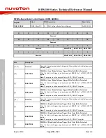
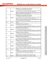
[29]
BRKLSTS5
PWM Channel 5 Level-detect Brake Status (Read Only)
0 = PWM channel 5 level-detect brake state is released.
1 = When PWM channel 5 level-detect brake detects a falling edge of any enabled brake
source; this flag will be set to indicate the PWM channel 5 at brake state.
Note:
This bit is read only and auto cleared by hardware. When enabled brake source return
to high level, PWM will release brake state until current PWM period finished. The PWM
waveform will start output from next full PWM period.
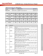
[28]
BRKLSTS4
PWM Channel 4 Level-detect Brake Status (Read Only)
0 = PWM channel 4 level-detect brake state is released.
1 = When PWM channel 4 level-detect brake detects a falling edge of any enabled brake
source; this flag will be set to indicate the PWM channel 4 at brake state.
Note:
This bit is read only and auto cleared by hardware. When enabled brake source return
to high level, PWM will release brake state until current PWM period finished. The PWM
waveform will start output from next full PWM period.
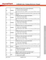
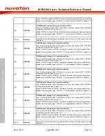
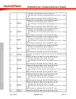
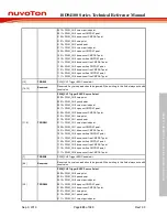
[27]
BRKLSTS3
PWM Channel 3 Level-detect Brake Status (Read Only)
0 = PWM channel 3 level-detect brake state is released.
1 = When PWM channel 3 level-detect brake detects a falling edge of any enabled brake
source; this flag will be set to indicate the PWM channel 3 at brake state.
Note:
This bit is read only and auto cleared by hardware. When enabled brake source return
to high level, PWM will release brake state until current PWM period finished. The PWM
waveform will start output from next full PWM period.
[26]
BRKLSTS2
PWM Channel 2 Level-detect Brake Status (Read Only)
0 = PWM channel 2 level-detect brake state is released.
1 = When PWM channel 2 level-detect brake detects a falling edge of any enabled brake
source; this flag will be set to indicate the PWM channel 2 at brake state.
Note:
This bit is read only and auto cleared by hardware. When enabled brake source return
to high level, PWM will release brake state until current PWM period finished. The PWM
waveform will start output from next full PWM period.


