ISD94100 Series Technical Reference Manual
Sep 9, 2019
Page
623
of 928
Rev1.09
IS
D
9
410
0
S
ER
IE
S
T
E
C
HN
ICA
L
RE
F
E
RE
NCE
M
AN
U
AL
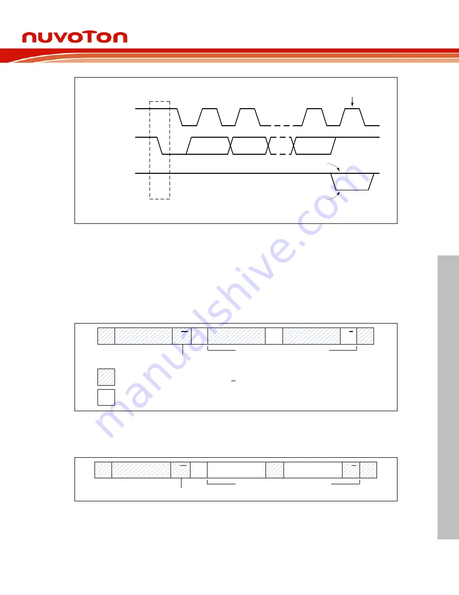
Data output by
transmitter
SCL from
master
START
condition
acknowlegde
Data output
by receiver
S
1
2
8
9
Clock pulse for
acknowledgement
not acknowlegde
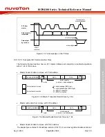
Figure 6.13-7 Acknowledge on the I
2
C Bus
6.13.5.1.5 Complete I2C Communication Flow
The following figures illustrate how an I2C master initiates and completes a read/write operation
with a 7-bit or 10-bit slave.
•
Master transmits data to a slave with 7-bit address
A = acknowledge (SDA low)
A = not acknowledge (SDA high)
S = START condition
P = STOP condition
‘0’ : write
S
SLAVE ADDRESS
R/W
A
DATA
A
DATA
A/A
P
from master to slave
from slave to master
data transfer
(n bytes + acknowlegde)
Figure 6.13-8 Master Transmits Data to Slave by 7-bit
•
Master reads data from a slave with 7-bit address
‘1’ : read
S
SLAVE ADDRESS
R/W
A
DATA
A
DATA
A/A
P
data transfer
(n bytes + acknowlegde)
Figure 6.13-9 Master Reads Data from Slave
by 7-bit
•
Master transmits data to a slave with 10-bit address
The header byte contains 10-bit address indicator (5’b11110), two most significant address bits and

