ISD94100 Series Technical Reference Manual
Sep 9, 2019
Page
688
of 928
Rev1.09
IS
D
9
410
0
S
ER
IE
S
T
E
C
HN
ICA
L
RE
F
E
RE
NCE
M
AN
U
AL
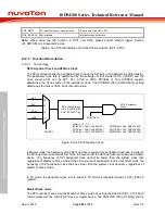
6.14.5.6 Slave 3-Wire Mode
When SLV3WIRE (SPI0_SSCTL[4]) is set by software to enable the Slave 3-Wire mode, the SPI
controller can work with no slave selection signal in Slave mode. The SLV3WIRE (SPI0_SSCTL[4])
only takes effect in Slave mode. Only three pins, SPI0_CLK, SPI0_MISO0, and SPI0_MOSI0, are
required to communicate with a SPI master. The SPI0_SS0 and SPI0_SS1 pin can be configured
as a GPIO. When the SLV3WIRE (SPI0_SSCTL[4]) is set to 1, the SPI slave will be ready to
transmit/receive data after the SPIEN (SPI0_CTL[0]) is set to 1.
Note:
This function is only supported in SPI0.
6.14.5.7 PDMA Transfer Function
SPI controller supports PDMA transfer function.
When TXPDMAEN (SPIn_PDMACTL[0]) is set to 1, the controller will issue request to PDMA
controller to start the PDMA transmission process automatically.
When RXPDMAEN (SPIn_PDMACTL[1]) is set to 1, the controller will start the PDMA reception
process. SPI controller will issue request to PDMA controller automatically when there is data in the
RX FIFO buffer.
Note:
SPI supports single request PDMA (Read/Write) only, burst request PDMA is not supported.
6.14.5.8 Two-Bit Transfer Mode
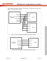
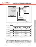
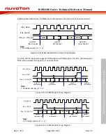
The SPI controller also supports 2-Bit Transfer mode when setting TWOBIT (SPI0_CTL[16]) to 1.
In 2-Bit Transfer mode, the SPI controller performs full duplex data transfer. In other words, the two
serial data bits can be transmitted and received simultaneously.
For example, in Master mode, the even data (TX Data (n)) stored in the SPI0_TX register will be
transmitted through the SPI0_MOSI0 pin and the odd data (TX Data (n+1)) stored in the SPI0_TX
register will be transmitted through the SPI0_MOSI1 pin respectively. In the meanwhile, the even
data received from SPI0_MISO0 pin will be written to RX FIFO prior to the odd data received from
SPI0_MISO1 pin.
In Slave mode, the even and odd data stored in the SPI0_TX register will be transmitted through
the SPI0_MISO0 pin and SPI0_MISO1 pin respectively. In the meanwhile, the SPI0_RX register
will store the even data received from the SPI0_MOSI0 pin and the odd data from SPI0_MOSI1 pin
respectively. The data sequence of FIFO buffers is the same as the Master mode.
Note:
This function is only supported in SPI0.

