ISD94100 Series Technical Reference Manual
Sep 9, 2019
Page
424
of 928
Rev1.09
IS
D
9
410
0
S
ER
IE
S
T
E
C
HN
ICA
L
RE
F
E
RE
NCE
M
AN
U
AL
16-bits PWM
3 types counter
PHSENn
(PWM_SYNC[2:0])
SINSRCn
(PWM_SYNC[13:8])
SWSYNCn
(PWM_SWSYNC[2:0])
PHS
(PWM_PHSn[15:0])
CNT
(PWM_CNTn[15:0])
DIRF
(PWM_CNTn[16])
SYNC_IN
SYNC_OUT
PHS load signal
0
1
2
3
CNT = 0
CNT = CMPDATm
Disabled
PHSDIRn
(PWM_SYNC[26:24])
Note:
n denotes channel 0, 2, 4
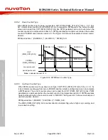
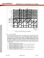
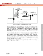
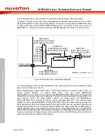
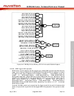
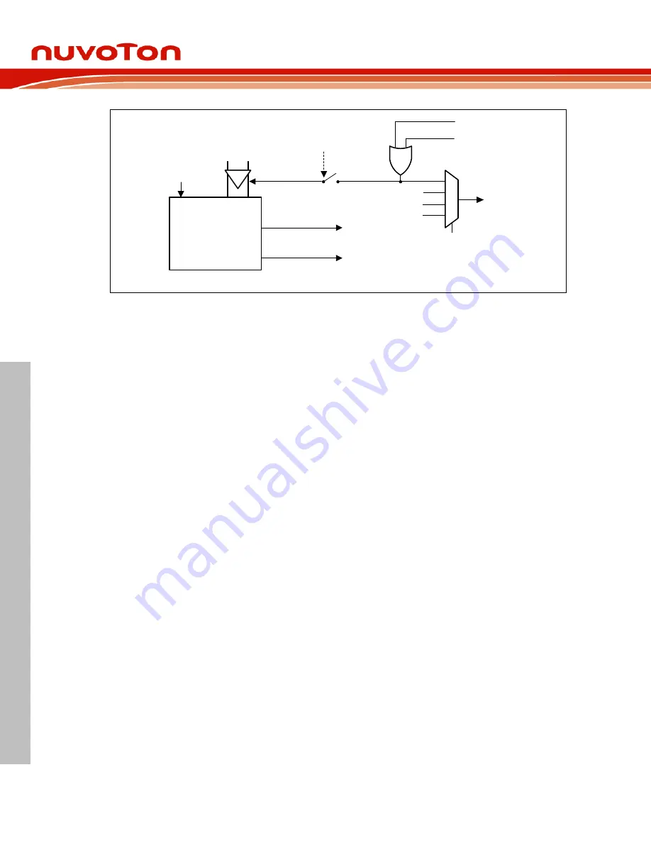
Figure 6.8-24
P
WM Counter Synchronous Function Block Diagram
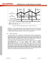
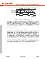
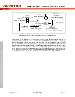
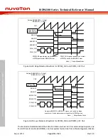
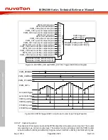
Figure 6.8-25 is an example of the synchronous function in the up-down counter type. In the
example, synchronizing source comes from the external PWM SYNC_IN signal. At the beginning,
the output waveform of PWM_CH0, PWM_CH2 and PWM_CH4 are in the same phase. Then at
Point A, the PWM SYNC input signal comes as a sync event, resulting in phase shifts and counting
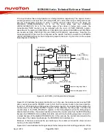
direction changes for all of the counters. To realize the altered counter behaviors before the sync
event coming, user has to setup the corresponding phase value in the PHS
of(PWM_PHSn_m[15:0]) as well as the counting direction in the PHSDIRn (PWM_SYNC[26:24]).
In this case, one third of phase shifts are made. by setting the corresponding channel n’s counter
counting direction after synchronizing, as illustrated around the left side of Figure 6.8-25.

