ISD94100 Series Technical Reference Manual
Sep 9, 2019
Page
577
of 928
Rev1.09
IS
D
9
410
0
S
ER
IE
S
T
E
C
HN
ICA
L
RE
F
E
RE
NCE
M
AN
U
AL
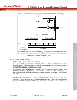
Power-down mode
UART0_CLK
UART0_RXD pin
DATWKF
UART_CLK stable count
CPU run
start
HCLK
stable count
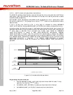
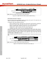
Note1:
Stable count means HCLK source recovery stable count.
Note2:
UART0_CLK stable count means UART clock source recovery stable count.
Figure 6.12-7 UART Data Wake-up
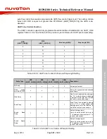
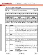
RX FIFO reaching threshold wake-up:
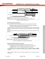
To setup the RX FIFO Reached Threshold Wake-up function, configure the following bits:
-
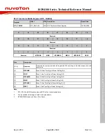
WKRFRTEN (UART_WKCTL[2]): RX FIFO Reached Threshold Wake-up Enable bit
-
RFITL (UART_FIFO[7:4]): RX FIFO Interrupt Trigger level
In power down mode, an event that the number of received data in RX FIFO reaches the threshold
value RFITL (UART_FIFO[7:4]) can wakeup the system, and flag RFRTWKF (UART_WKSTS[2])
will be set.
Note:
The UART controller clock source should be choose LXT in power down mode for data
receiving.
Power-down mode
HCLK
RFRTWKF
Start
DATA0
DATA1
RX FIFO number reached RFITL
UART0_RXD pin
DATAx
stable
count
Note:
Stable count means HCLK source recovery stable count.
Figure 6.12-8 UART RX FIFO reached threshold wake-up
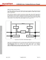
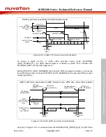
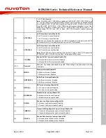
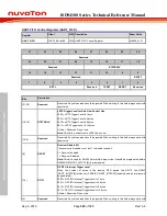
RS-485 Address Matching (AAD mode) wake-up:
Enable the following bits to setup RS-485 address matching wake-up function:
-
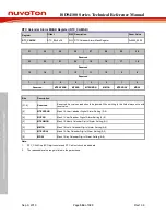
WKRS485EN (UART_WKCTL[3]): RS-485 Address Match Wake-up Enable bit
-
ADDRDEN (UART_ALTCTL[15]): Rs-485 Address Detection Enable bit
In Power-down mode, when an address byte is detected matching ADDRMV
(UART_ALTCTL[31:24]), flag RS485WKF (UART_WKSTS[3]) will be raised and thus wakes up
the system.
Note:
The UART controller clock source should be selected as LXT in Power-down mode to
receive data.

