ISD94100 Series Technical Reference Manual
Sep 9, 2019
Page
739
of 928
Rev1.09
IS
D
9
410
0
S
ER
IE
S
T
E
C
HN
ICA
L
RE
F
E
RE
NCE
M
AN
U
AL
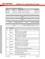
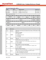
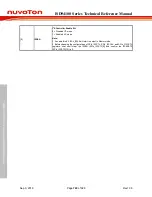
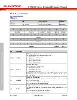
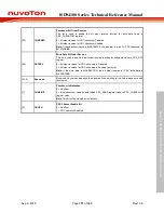
[17]
FLZCDEN
Force Left Channel Zero Cross Data Option Bit
If this bit is set to 1, when left channel data sign bit changes or next shift data bits are all 0
then LZCIF flag in SPIn_I2SSTS register is set to 1 and left channel data will force zero.
This function is only available in transmit operation.
0 = Keep Left channel data, when zero crossing flag on.
1 = Force Left channel data to zero, when zero crossing flag on.
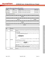
[16]
FRZCDEN
Force Right Channel Zero Cross Data Option Bit
If this bit is set to 1, when right channel data sign bit change or next shift data bits are all 0
then RZCIF flag in SPIn_I2SSTS register is set to 1 and right channel data will force zero.
This function is only available in transmit operation.
0 = Keep Right channel data, when zero crossing flag on.
1 = Force Right channel data to zero, when zero crossing flag on.
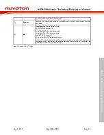
[15]
MCLKEN
Master Clock Enable Bit
If MCLKEN is set to 1, I
2
S controller will generate master clock on SPIx_I2SMCLK pin for
external audio devices.
0 = Master clock Disabled.
1 = Master clock Enabled.
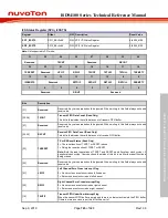
[14:9]
Reserved
Reserved. Any values read should be ignored. When writing to this field always write with
reset value.
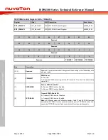
[8]
SLAVE
Slave Mode
I
2
S can operate as master or slave. For Master mode, I2Sx_BCLK and I2Sx_LRCLK pins
are output mode and send bit clock from ISD94100 series to audio CODEC chip. In Slave
mode, I2Sx_BCLK and I2Sx_LRCLK pins are input mode and I2Sx_BCLK and I2Sx_LRCLK
signals are received from outer audio CODEC chip.
0 = Master mode.
1 = Slave mode.
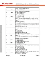
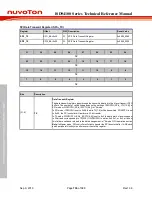
[7]
ORDER
Stereo Data Order in FIFO
0 = Left channel data at high byte.
1 = Left channel data at low byte.
[6]
MONO
Monaural Data
0 = Data is stereo format.
1 = Data is monaural format.
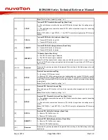
[5:4]
WDWIDTH
Word Width
00 = data size is 8-bit.
01 = data size is 16-bit.
10 = data size is 24-bit.
11 = data size is 32-bit.
[3]
MUTE
Transmit Mute Enable Bit
0 = Transmit data is shifted from buffer.
1 = Transmit channel zero.
[2]
RXEN
Receive Enable Bit
0 = Data receive Disabled.
1 = Data receive Enabled.
[1]
TXEN
Transmit Enable Bit
0 = Data transmit Disabled.
1 = Data transmit Enabled.


