ISD94100 Series Technical Reference Manual
Sep 9, 2019
Page
55
of 928
Rev1.09
IS
D
9
410
0
S
ER
IE
S
T
E
C
HN
ICA
L
RE
F
E
RE
NCE
M
AN
U
AL
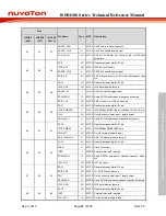
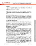
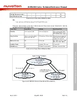
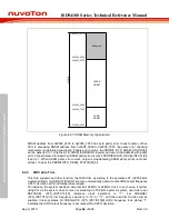
Normal mode
The system starts up in Normal mode. All clock sources and peripheral can be enabled or disabled
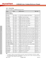
by user in register CLK_PWRCTL (System Power-down Control Register), CLK_AHBCLK (AHB
Devices Clock Enable Control Register), CLK_APBCLK0 (APB Devices Clock Enable Control
Register 0) and CLK_APBCLK1 (APB Devices Clock Enable Control Register 1). The user can
disable unused clock or peripheral to save power.
Idle mode
If system is waiting for an interrupt only. The user can set system in idle mode. In idle mode, only
CPU clock is disabled, other peripherals work normally. System waits interrupt to wake-up, returns
to Normal mode and program execution continues. All interrupts can wake-up system from Idle
mode.
Power-down mode (PD)
In Power-down mode (PD), CPU clock is disabled and LDO enters low power mode. All clock source
will be disabled except LXT and LIRC, LXT and LIRC can be controlled by CLK_PWRCTL register.
If they are enabled and peripheral clock source are selected as LXT or LIRC, the peripheral can
keep working in Power-down mode. System waits wake-up source occurred to wake-up, returns to
Normal mode and program execution continues. In system wake-up phase, system waits for LDO
recovery, and clock sources are enabled again and stable.
Low Leakage Power-down mode (LLPD)
In Low Leakage Power-down mode (LLPD), CPU clock is disabled, LDO enters low power mode
and LDO voltage drops down from current working voltage to 0.9 V to save power. All clock source
will be disabled except LXT and LIRC, LXT and LIRC can be controlled by CLK_PWRCTL register.
If they are enabled and peripheral clock source are selected as LXT or LIRC, the peripheral can
keep working in Low Leakage Power-down mode. System waits wake-up source occurred to wake-
up, returns to Normal mode and program execution continues. In system wake-up phase, besides
waiting for LDO recovery and clock sources are enabled and stable, system also needs to wait for
LDO voltage rising to the original working voltage. The Low Leakage Power-down mode wake-up
sources are the same as Power-down mode.
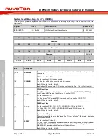
Standby Power-down mode 0 (SPD0)
In Standby Power-down mode 0 (SPD0), all power supply is disabled except SPD0 control logic,
LXT and LIRC. The SPD0 control logic controls Standby Power-down mode wake-up functions and
system SRAM bank0 to retain data. After wake-up from Standby Power-down mode 0 (SPD0),
system resets and executes code from the beginning again. All peripheral configurations return to
default value and all SRAM data will be lost except system SRAM bank0 data can be retained.
After system wake-up from Standby Power-down mode 0 (SPD0), GPIO will keep their states before
entering Standby Power-down mode 0. They cannot be controlled by GPIO or peripherals register
after system wake-up, for example: UART cannot print message and ICE cannot download code.
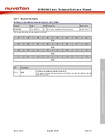
To control GPIO, the user have to write 1 to register CLK_IOPDCTL (GPIO Standby Power-down
Control Register) after system wake-up to release GPIO hold state function.
Standby Power-down mode 1 (SPD1)
In Standby Power-down mode 1 (SPD1), all power supply is disabled except SPD1 control logic,
LXT and LIRC. The SPD1 control logic controls Standby Power-down mode wake-up functions.
After wake-up from Standby Power-down mode 1 (SPD1), system resets and executes code from
the beginning again. All peripheral configurations return to default value and all SRAM data will be
lost.
After system wake-up from Standby Power-down mode 1 (SPD1), GPIO will keep their states before
entering Standby Power-down mode 1. They cannot be controlled by GPIO or peripherals register
after system wake-up, for example: UART cannot print message and ICE cannot download code.
To control GPIO, the user have to write 1 to register CLK_IOPDCTL (GPIO Standby Power-down
Control Register) after system wake-up to release GPIO hold state function.

