ISD94100 Series Technical Reference Manual
Sep 9, 2019
Page
666
of 928
Rev1.09
IS
D
9
410
0
S
ER
IE
S
T
E
C
HN
ICA
L
RE
F
E
RE
NCE
M
AN
U
AL
[8]
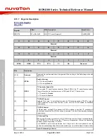
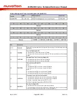
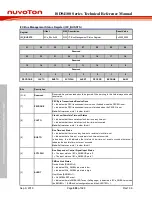
PECTXEN
Packet Error Checking Byte Transmission/Reception
0 = No PEC transfer.
1 = PEC transmission is requested.
Note:
1.This bit has no effect in slave mode when ACKMEN =0.
[7]
BUSEN
BUS Enable Bit
0 = The system management function is Disabled.
1 = The system management function is Enable.
Note:
When the bit is enabled, the internal 14-bit counter is used to calculate the time out
event of clock low condition.
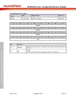
[6]
SCTLOEN
Suspend or Control Pin Output Enable Bit
0 = The I2Cn_SMBSUS pin in input.
1 = The output enable is active on the I2Cn_SMBSUS pin.
[5]
SCTLOSTS
Suspend/Control Data Output Status
0 = The output of I2Cn_SMBSUS pin is low.
1 = The output of I2Cn_SMBSUS pin is high.
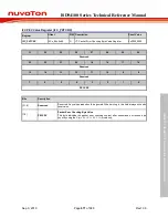
[4]
ALERTEN
Bus Management Alert Enable Bit
Device Mode (BMHEN =0).
0 = Release the I2Cn_SMBAL pin high and Alert Response Header disabled: 0001100x
followed by NACK if both of BMDEN and ACKMEN are enabled.
1 = Drive I2Cn_SMBAL pin low and Alert Response Address Header enables: 0001100x
followed by ACK if both of BMDEN and ACKMEN are enabled.
Host Mode (BMHEN =1).
0 = I2Cn_SMBAL pin not supported.
1 = I2Cn_SMBAL pin supported.
[3]
BMHEN
Bus Management Host Enable Bit
0 = Host function Disabled.
1 = Host function Enabled.
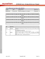
[2]
BMDEN
Bus Management Device Default Address Enable Bit
0 = Device default address Disable. When the address 0’b1100001x coming and the both
of BMDEN and ACKMEN are enabled, the device responses NACKed
1 = Device default address Enabled. When the address 0’b1100001x coming and the both
of BMDEN and ACKMEN are enabled, the device responses ACKed.
[1]
PECEN
Packet Error Checking Calculation Enable Bit
0 = Packet Error Checking Calculation Disabled.
1 = Packet Error Checking Calculation Enabled.
Note:
When I
2
C enter powerdown mode, the bit should be enabled after wake-up if needed
PEC calculation.
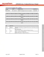
[0]
ACKMEN
Acknowledge Control by Manual
In order to allow ACK control in slave reception including the command and data, slave byte
control mode must be enabled by setting the ACKMEN bit.
0 = Slave byte control Disabled.
1 = Slave byte control Enabled. The 9th bit can response the ACK or NACK according the
received data by user. When the byte is received, stretching the SCLK signal low between
the 8th and 9th SCLK pulse.
Note:
If the BMDEN =1 and this bit is enabled, the information of I2C_STATUS will be fixed
as 0xF0 in slave receive condition.

