ISD94100 Series Technical Reference Manual
Sep 9, 2019
Page
350
of 928
Rev1.09
IS
D
9
410
0
S
ER
IE
S
T
E
C
HN
ICA
L
RE
F
E
RE
NCE
M
AN
U
AL
transition of INTR_TMR_TRG. Then Timer0/2 counter mode function will be disabled and
INTRGEN (TIMERx_CTL[19]) will be cleared by hardware then Timer1/3 will stop counting also. At
the same time, the Timer1/3 CNT value will be saved into Timer1/3 CAPDAT (TIMERx_CAP[23:0]).
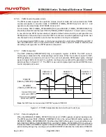
User can use inter-timer trigger mode to measure the period of external event (TMx) more precisely.
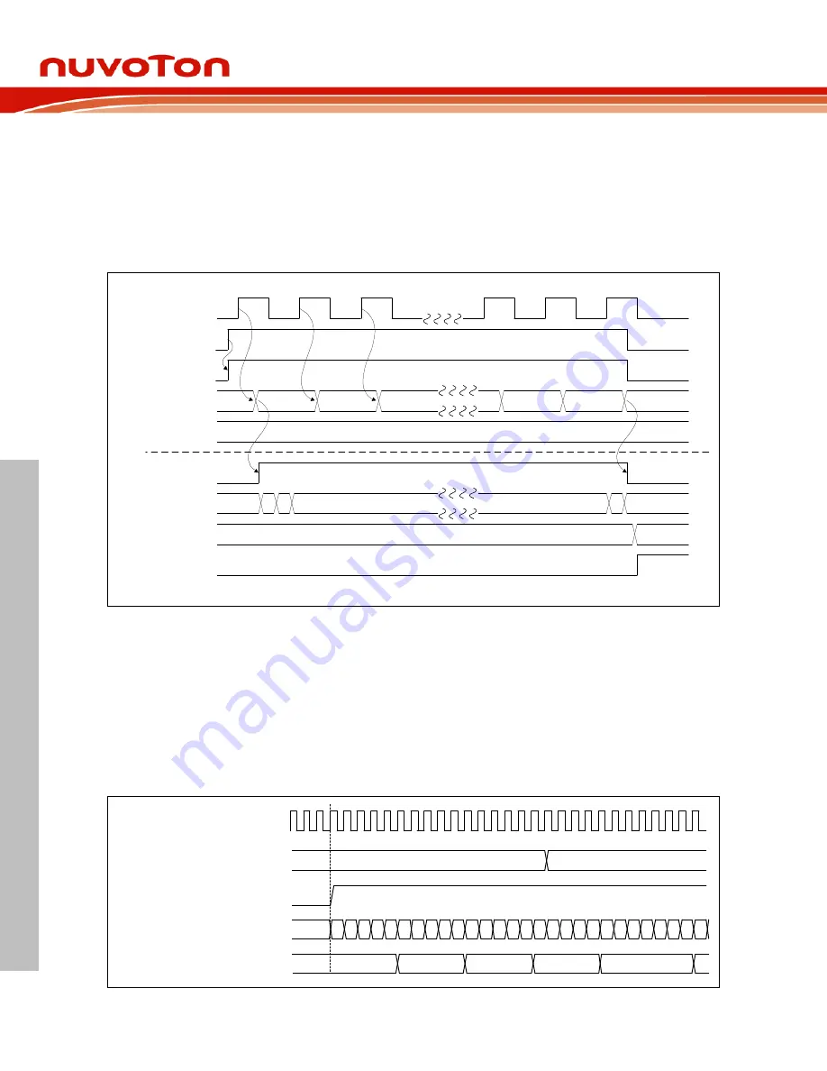
Figure 6.7-12 shows the sample flow of Inter-Timer Trigger Capture Mode for Timer0 as event
counting mode and Timer1 as trigger-counting capture mode.
TM0 pin
TIMR0 INTRGEN
TIMR0 EXTCNTEN
TIMR0 CNT
0
1
2
3
99
100
TIMR1 INTR_TMR_TRG
TIMR0 CMPDAT
100
0
TIMR1 CNT
0
1
2
998
999
TIMR1 CAPDAT
999
TIMR1 CAPIF
Figure 6.7-12 Inter-Timer Trigger Capture Timing
6.7.6
PWM Functional Description
6.7.6.1
PWM Prescale
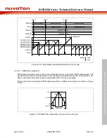
The PWM prescale is used to divide clock source, and the clock of PWM counter is divided by
( 1). The prescale is set by CLKPSC (TIMERx_PWMCLKPSC[11:0]). Figure 6.7-13
shows an example of PWM prescale waveform in up count type.
0
1
PWMCNT
(TIMERx_PWMCNT[15:0])
4
Prescale counter
CLKPSC
(TIMERx_PWMCLKPSC[11:0])
3 2 1 0
3
PWMCNTEN
(TIMERx_PWMCTL[0])
4 3 2 1 0 4 3 2 1 0
5 4 3 2 1
6
0
0
2
4
6
TMRx_PWMCLK
4
6
4 3 2 1 0
x

