ISD94100 Series Technical Reference Manual
Sep 9, 2019
Page
345
of 928
Rev1.09
IS
D
9
410
0
S
ER
IE
S
T
E
C
HN
ICA
L
RE
F
E
RE
NCE
M
AN
U
AL
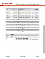
TM0
PD.8
MFP2
PD.2
MFP5
TM0_EXT
PA.12
MFP2
PD.9
MFP2
TM1
TM1
PA.14
MFP2
PD.4
MFP5
TM1_EXT
PA.15
MFP2
6.7.4.2 TIMER23 basic configurations
Clock source configuration
–
Enable TIMER2 peripheral clock in TMR2CKEN (CLK_APBCLK0[4]).
–
Enable TIMER3 peripheral clock in TMR2CKEN (CLK_APBCLK0[5]).
Reset configuration
–
Reset TIMER2 controller in TMR2RST (SYS_IPRST1[4]).
–
Reset TIMER3 controller in TMR3RST (SYS_IPRST1[5]).
Pin configuration
Group
Pin Name
GPIO
MFP
TM2
TM2
PB.2
MFP2
PD.3
MFP5
TM2_EXT
PB.3
MFP2
TM3
TM3
PC.2
MFP2
TM3_EXT
PC.3
MFP2
6.7.5
Timer Functional Description
6.7.5.1
Timer Interrupt Flag
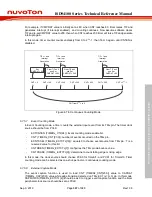
In timer mode, Timer controller can generate the two interrupts:
-
Timer Interrupt: TIF (TIMERx_INTSTS[0]) bit will be set when timer counter value CNT
(TIMERx_CNT[23:0]) matches the timer compared value CMPDAT (TIMERx_CMP[23:0]);
-
Timer External Capture Interrupt: CAPIF (TIMERx_EINTSTS[0]) bit will be set when a
transition that matches CAPEDGE (TIMERx_EXTCTL[14:12]) setting is detected on the
TMx_EXT pin.
TWKF (TIMERx_INTSTS[1]) bit will be set if a timer mode interrupt wakes up the system. Writing
1 to this bit clears the flag.
6.7.5.2
Timer Counting Mode
Timer controller provides four timer counting modes: one-shot, periodic, toggle-output and


