ISD94100 Series Technical Reference Manual
Sep 9, 2019
Page
69
of 928
Rev1.09
IS
D
9
410
0
S
ER
IE
S
T
E
C
HN
ICA
L
RE
F
E
RE
NCE
M
AN
U
AL
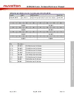
Bits
Description
[4]
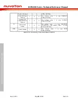
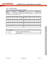
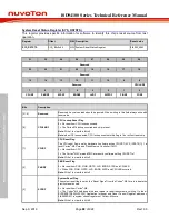
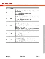
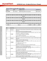
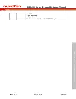
BODRF
BOD Reset Flag
The BOD reset flag is set by the “Reset Signal” from the Brown-Out Detector to indicate the
previous reset source.
0 = No reset from BOD.
1 = The BOD had issued the reset signal to reset the system.
Note:
Write 1 to clear this bit to 0.
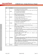
[3]
LVRF
LVR Reset Flag
The LVR reset flag is set by the “Reset Signal” from the Low Voltage Reset Controller to
indicate the previous reset source.
0 = No reset from LVR.
1 = LVR controller issued the reset signal to reset the system.
Note:
Write 1 to clear this bit to 0.
[2]
WDTRF
WDT Reset Flag
The WDT reset flag is set by the “Reset Signal” from the Watchdog Timer or Window
Watchdog Timer to indicate the previous reset source.
0 = No reset from watchdog timer or window watchdog timer.
1 = The watchdog timer or window watchdog timer issued the reset signal to reset the
system.
Note1:
Write 1 to clear this bit to 0.
Note2:
Watchdog Timer register RSTF(WDT_CTL[2]) bit is set if the system has been reset
by WDT time-out reset. Window Watchdog Timer register WWDTRF(WWDT_STATUS[1])
bit is set if the system has been reset by WWDT time-out reset.
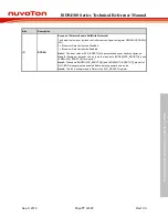
[1]
PINRF
NRESET Pin Reset Flag
The nRESET pin reset flag is set by the “Reset Signal” from the nRESET Pin to indicate the
previous reset source.
0 = No reset from nRESET pin.
1 = Pin nRESET issued the reset signal to reset the system.
Note:
Write 1 to clear this bit to 0.
[0]
PORF
POR Reset Flag
The POR reset flag is set by the “Reset Signal” from the Power-on Reset (POR) Controller
or bit CHIPRST (SYS_IPRST0[0]) to indicate the previous reset source.
0 = No reset from POR or CHIPRST.
1 = Power-on Reset (POR) or CHIPRST issued the reset signal to reset the system.
Note:
Write 1 to clear this bit to 0.

